My O Gauge Journal on
Modelling the GWR
A personal Journey
2017 update
Adding new locos to the stock list
Its important to recognise that not all locos are the same and will be have in the same manner. This is due to many things like the type of motors in use the gearing the friction on the gearing and wheel configurations. Because of these 'variables' its important to keep a CV bible. Each loco is documented re its CV lists and as a basic area I keep the following values for each loco.
The following CVs are common to most locos regardless of which
system you use, (apologies if grannies and egg sucking is involved
here!)
1 (loco address – set to 3 by default range is
1-127)
2 (Start voltage – sets the minimum speed of the engine range 1-255)
3 (Acceleration – value x 0.25 time from stop to maximum speed range
0-255)
4 (Deceleration – value x 0.25 time from maximum speed to stop range
0-255)
5 (Maximum speed)
6 (Medium speed)
53 (defines the back EMF of the motor range 0 – 255)
54 (defines the effect of load control: used if loco lurches on
stopping range 0-255)
55 (defines the effect of load control: used if loco lurches on
starting range 0-255)
56 (operating range of load control try 64 range 1-255)
57 (Steam chuff sync 1 – needs more explanation!)
58 (Steam chuff sync 2 – needs more explanation!)63 (Master sound
volume for all sounds)
Finally, its often the case that by changing a couple of CVs you can change the behaviour of your loco, lurching at startup or stopping for instance).
In the last months the base controller has been upgraded to a 611 unit. Amongst other things the separate computer interface unit is now redundant as its integral with the base unit. I have also inherited an old iPad which has been setup with WiThrottle and works alongside the other controllers wirelessly.
Update on DCC control:
The current system a ZTC505 base controller now has a PC interface and JMRI software introduced to it. This will enable me to use an iPod touch to control locos wirelessly.
Click on images for a larger view.
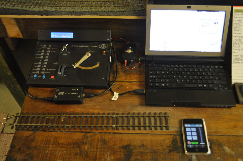
Here are the component parts: a laptop, an iPod touch, a PC interface and the software from JMRI, (which is free and has a lot of online support albeit in the states and australia).
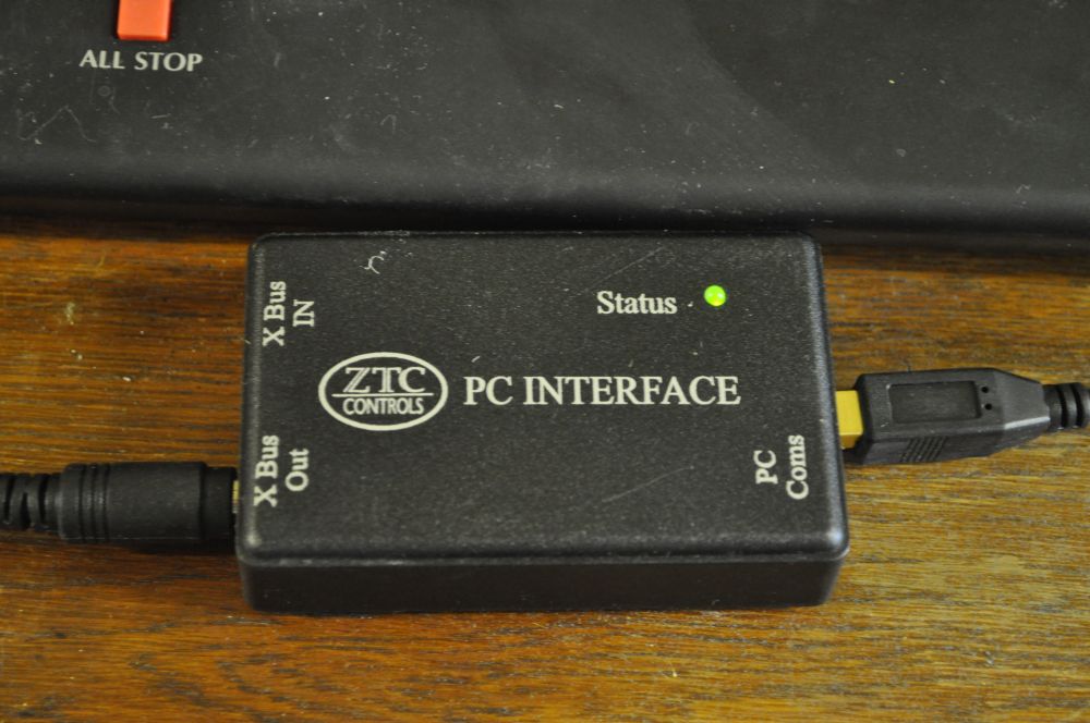
The interface is a ZTC product and connects from the Xbus socket on the base controller and to a USB port on the laptop. There is also an extra Xbus socket to allow a handheld controller to be fitted. Thus my layout can have 3 controllers working independantly.
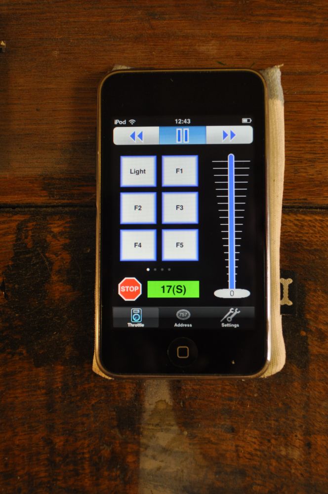
The iPod Touch connects wirelessly to the laptop through the wireless router that supplies internet connectivity for the house etc. and has an app, (which is free), that makes it into a WiController.
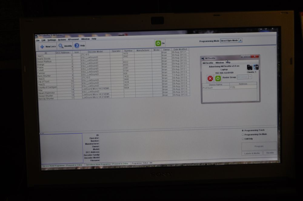
The software from JMRI, enables you to identify each locos decoder, connect it to a throttle and match it to a similar throttle on the iPod Touch. The iPod touch app also has function buttons that work as well and you can select the loco to drive from a list on the iPod screen, (this skips the need to know the address of the loco) .
Initially, I set up the locos on my laptop before I had the PC interface and I had to guess which decoders they had fitted in them. But on a first trial all seemed to work ok. There are limitations with the software and the type of pc interface and decoders in use and the ZTC one really only has control capability and not much else, (you can't set CVs or use the program track). But I am investigating the extent to which the laptop software can control the decoders.
All my locos are chipped and work with DCC technology. It must be the easiest way of running a model railway as there is no need for isolation sections in the track. The prime downside is cost. I use the German made Locksound DCC and sound chips which I buy from Howes Models and at £170 a shot they are rather expensive, but the attention to sound detail and quality is exceptional. Everything is there down to brake squeal! And each loco is different as sound samples have been taken from our preserved railway sights.
I had used the ZTC chips with sound until the company was bought out, and now I find they cannot be replaced. Also all the sounds are the same on the ZTC chips so a pannier makes the same sounds as a castle! Also if they go wrong and cannot be fixed there are currently no replacements available. Having said that the controllers I use are all ZTC and they are excellent. I have a 505 commander central control and a hand held control. Nice thing about these is that they sport a regulator lever not a knob or touch buttons. Just two wires to the track is all that is needed and each loco has its own unique address and can be dialled or selected from a list into action.
So first things first. DCC does not require the layout to be sectioned. But it does require you to think about electrifying it. Turnouts can be an issue and I have detailed how I connect them elsewhere on my site. What you want to avoid is any situation where turnouts might cause a short circuit and overload the system. Turnouts can also direct current along lines according to its setting. This means that throwing a switch can cut out the sound of a loco and render it 'switched off'. Useful in terms of safety but its also possible to have current running everywhere regardless of how turnouts are set. \so even before we get to the locos there is a deal of thinking to be done.
So thus said, how do you fit a chip. Often an issue because of space and because I need a control chip that will drive O gauge locos with enough amperage to work the motors of these large heavy machines. 00 gauge will let you get away with 0.5 - 1 amps so the little chips that Lenz do are fine. but O gauge is looking at up to 3 amps and larger ones are a must if you don't want to see your money literally go up in smoke.
This is how I fitted a chip into my Tower model pannier:
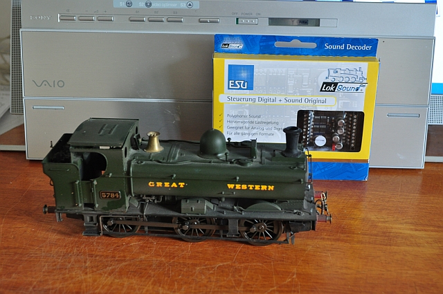 Starting with the loco and the chip. I had already used a mockup to see where I could fit the chip. It comes in at a hefty 51mm x 40mm x 14mm so a tank engine is usually a big challenge, (if a loco has a tender it goes in there). The speaker will go in the cab and the chip will just fit in the top of the loco above the motor. |
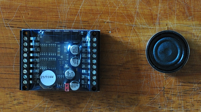 This is what we are talking about. I cut the end pieces off so it is 51mm x 40mm x 14mm. The speaker is a mid sized one. The larger one has a baffle back. |
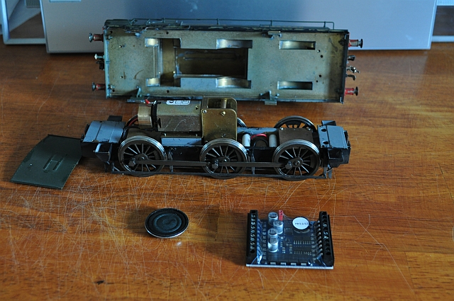 So take the engine apart from its body. There are 6 connections you have to make and 4 of these come when the motor leads are unsoldered. So two will go to the motor and the other two will go to the rails. Finally two go to the loudspeaker. In simple terms, you are putting the chip between the rails and the motor and also connecting the chip to a loudspeaker. |
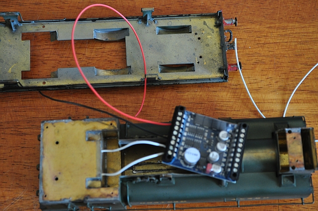 The two white leads on the right are for the loudspeaker. They go through the backplate wall into the cab where the loudspeaker is to be sighted. The red and black leads in the picture are for the motor. The place where t he chip is to be housed must be isolated so nothing can short circuit any components on it, (this is really important!). |
All is not over when the final leads have been connected. All the chips come with the loco value, (CV1), set to 3.
If you have more that one loco you will need to reset that value to something else. The ZTC equipment has instructions on how to do that. Unfortunately, the chip sound side started to play up after a couple of outings by spitting loudly over the sounds. Then no sound at all. I returned the board and was given a replacement. This one i decided to put in the bunker with the speaker in the boiler instead.
A video of the end result is shown below. Press the play button to view it.
If you have any questions about DCC you can email me on mail@bpodmore.co.uk
DCC Control
Two elements that I regard important is the ability to run more than one loco on the same stretch of line and to give them more life by adding sound to them. The DCC chips I use have that capability.