O Gauge Modelling on the GWR
A personal Journey
Just Like the real things 0-6-2
After a long wait I've decided to make a start on the above loco. The latest issue of the GWR Railway Journal has a fine article about this beast so it was timely to start on it.
Out of the box here are the body etchings. Click any image to see a larger version of it.
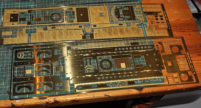
The instructions are very well illustrated with large drawings which make it an easy job to put it all together. The instructions however do not relate to the drawings in the same order so care is needed in following the instructions not the other way round.
Here is the body assembled with the strengthening structure in place.
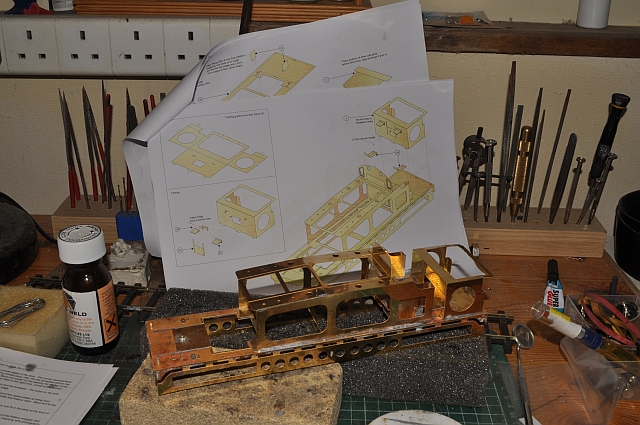
You can see a page of the illustrations in the background, very helpful. All parts referred to are numbered on the illustrations but not on the etch or an accompanying picture so they take some finding. A fairly high level of soldering skill is also necessary as the kit makes use of laminated pieces to give good detail. I used a combination of blow torch and paste and iron and low melt solder.

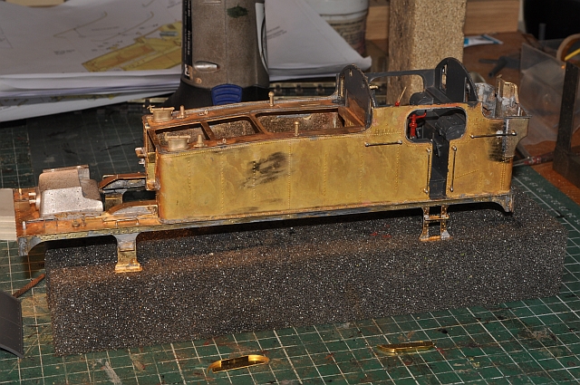
The detail is enhanced by the use of laminated sections for the sides top and rear of the loco. These need soldering in place and although fiddly look the part. I now see the instructions and illustrations as loose guides as neither one or the other seems to be concurrent with what needs to be done. further more some items are not numbered correctly or even at all and therefore difficult to identify. Here my loco has the sides and cab sections built and the forward windows and their frames in place. I can see that there is an opportunity here for the rivet counter to create his ideal loco. But I'm just building mine the best i can. At regular intervals i clean the body with Flash cleaner. This seems to remove the flux that gets everywhere when soldering.
Put together the castings for the front windows with clear cellophane inserts. Decided not to have them open/shut which you could do if wanted. You can just see one in the image below.

Shaping the back is not easy. I chose to put in a straight back then grind it away to accommodate the curved section. this image looks a little grim but there is a fair amount of filler involved here, which will all be ground away after drying.

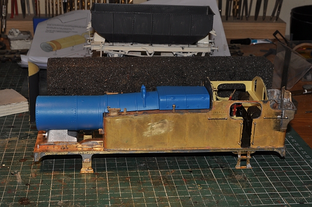
The tank top overlays and tank rivet strips are soldered in place. This kit has both the brass and preformed boilers. But it seems that on trying the preformed boiler that the front is out of kilter by somewhat. Looks like it has to be cut toward the front at an angle and shaped to fit parallel to the footplate. in one piece it definitely is not correct.

As you can see here the boiler is completely wrong, but after contacting JLTRT they are sending a replacement as it is quite unusual to see one like this!
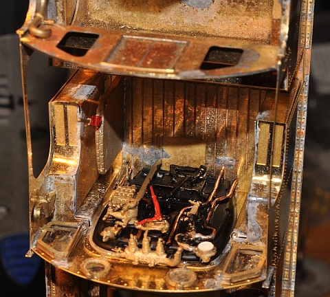
The backplate is now completed and insitu.

The cab roof is made up but not fixed as the inside will need painting etc as yet. The front and back edges of the cab roof and their associated riveted sections on the body just underneath have also been fitted. The sandbox levers and associated brackets some of which i had to make up are also in place.
The strengthening frame has now been removed. The footplate steps built and soldered in place and the side handrails made up and stuck in place. The cab has been given a little attention with a grey primer and will be left to dry for a couple of days. The rear handrails and the equalising pipe covers which fit behind the rear footsteps will be fitted next then there are several other fine detailed parts to fit such as the injector assembly, steam brake pipes and related parts and3 link couplings and gear.
The replacement boiler arrived today, with the correct orientation at the smokebox end, (compare this with the image further up). Grateful thanks to JLTRT for replacing it foc!
Unfortunately, the smokebox door appears to be competely wrong for both the original brass boiler and the resin one. See below:
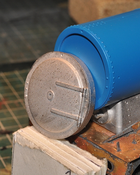
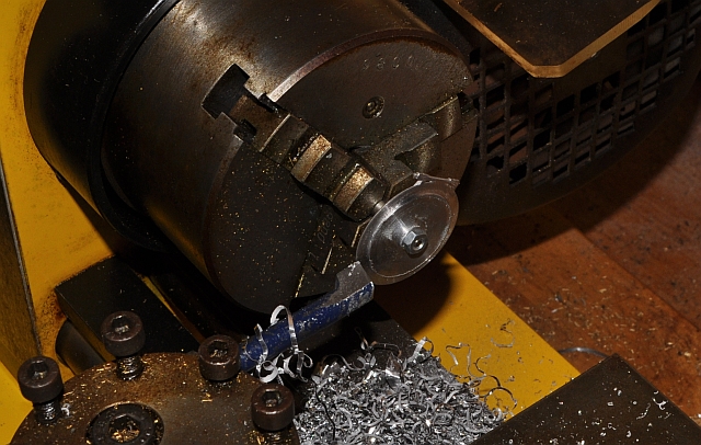
Fortunately, i was able to hone down the extra whitemetal banding to the rear of the door on the lathe.
This is the end result which is fine. The only casualty is the central hole which had to be enlarged to take a spindle, but will be filled when the locking arms are put in place.

Having resolved the smoke box door issue I finished of the chimney and other parts and stuck them in place.
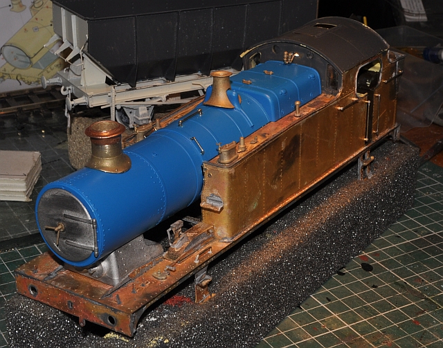
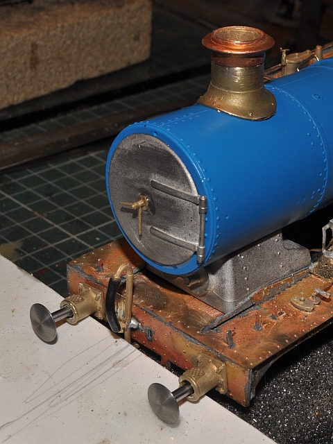
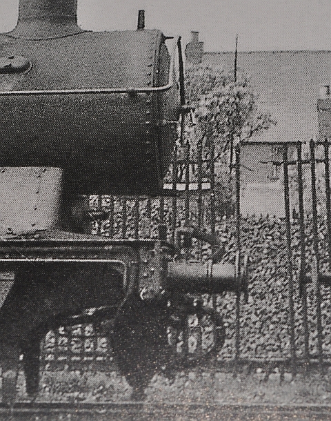
Well I thought my troubles were over but it seems not so. The buffers are the wrong type for a loco as you can see here. They would be more at home on wagon, (compare with the image below).
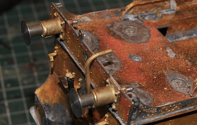
Amazing, there were apparently buffer shanks in the kit to make them up to the correct diameter! After a fair amount of boring and fettling to get them to fit here they are in place. (there were no subtle clues in the kit instructions or illustrations as to what those little sleeves were for and they were not the correct size to even try, but as you will see here they seem to fit ok.
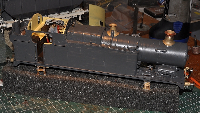
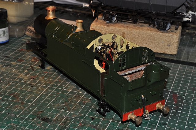
Having finished all the fittings on the body now including the couplings, it was time to give it a primer coat of grey.
Now in the paintshop and undergoing its third coat of colour and an application of buffer red.
Made a start on the chassis. I will be using sprung horn blocks. No mention of these as options is made in the instructions so i will have to experiment with positioning etc even though the chosen horn blocks are JLTRT products.
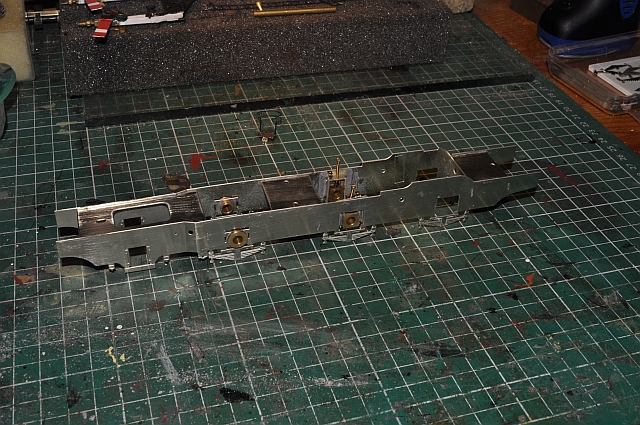
I haven't catalogued the making up of the chassis as it took a lot of decision making, (I didn't include the laminated sides of the chassis for instance as this would have made navigating the curves on my layout impossible. Also after painting it and adding frame dirt it makes any detail on the chassis irrelevant). There were no instructions regarding the fitting of the wheels and two sets of my wheels are on sprung horn blocks, as mentioned above. No parts for wiring it up even for conventional two rail supply but not a problem really. So this is what it now looks like:


It has had a preliminary run to check for smooth running and any short circuits, ( the front and rear wheel guards are very close to the track and need adjusting). Now i will complete this project with loksound board so that it will run on my DCC system.