My O Gauge Journal on
Modelling the GWR
A personal Journey
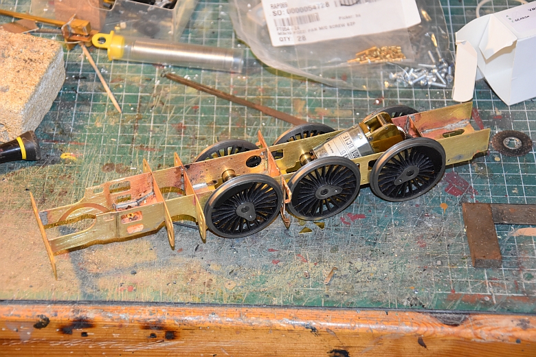
Made up the frames and wheel and motor mounting unit as per suggestions in Warren's notes. Here they are:
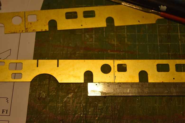
measuring the position of the rear cylinder profile which should be equidistant between the front and middle wheel bearings. Wheel centres were 49mm.
The frames soldered up with the cylinder profiles in place. The frame is not joggled.
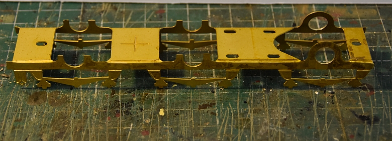
The wheel and motor mounting unit folded up. The rear bearing holes needed a little fettling.
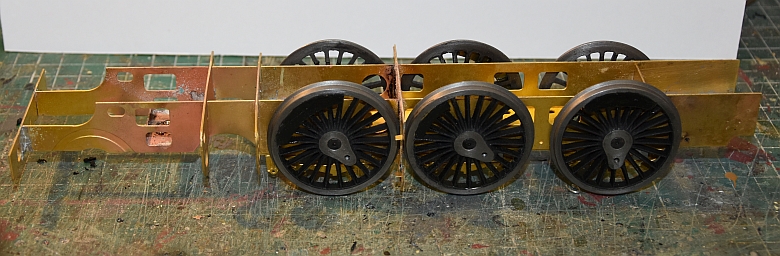
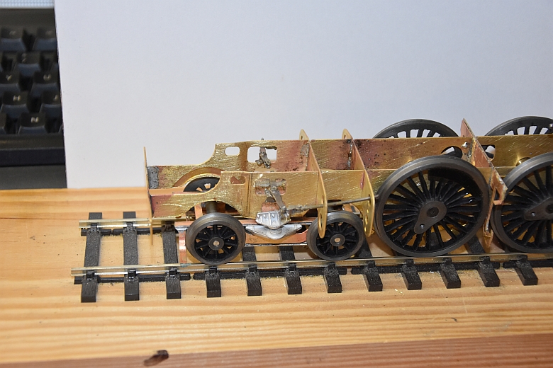
Checking for squareness, I used the wheels and axles as shown here. My only concern is how to allow for the 6ft radius curves on my railway. I will have to arrange for more play on these axles.
Having tried the arrangement on the tracks the middle and front wheel sets bind with the rear chassis support. I modified the inside slots to stop this happening and now the arrangement happily takes the curves on my DCC layout without shorting. Click the image below to see how this was achieved.
![]()
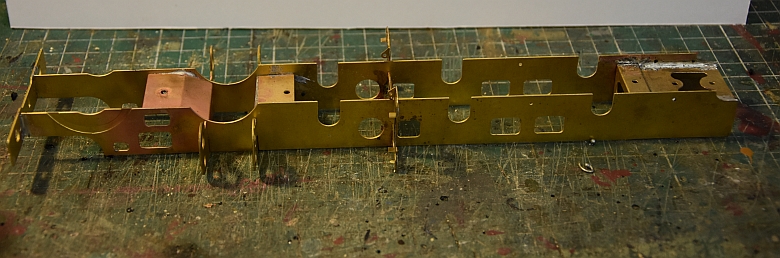
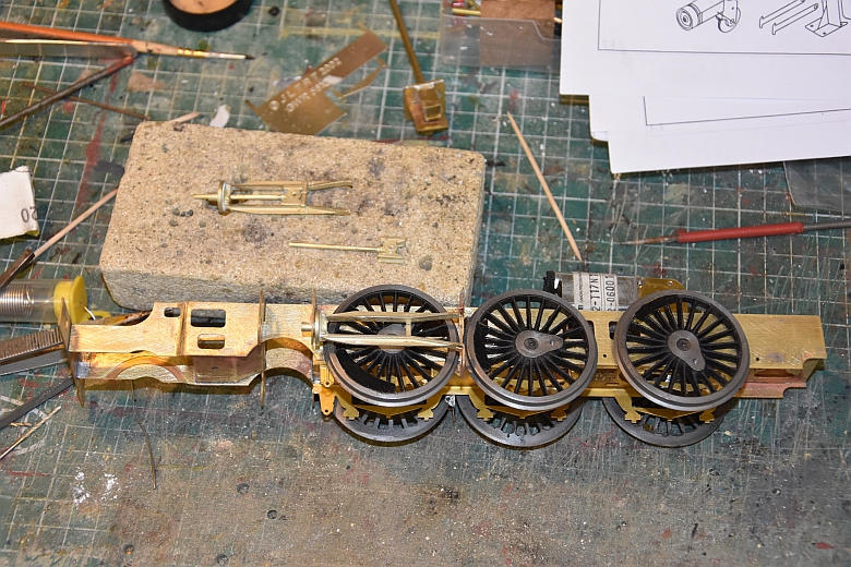
Dishing and joggling was something I forgot about when making up the frames, (as shown above, click on the image for a larger view). If joggling then this would suit an earlier engine. Easier to do than dishing as well and as my locomotive will be the early renamed Windsor Castle as Bristol Castle that was the way to go. So take it all apart as the frames were the wrong way round, joggle the front end of the frames and put the whole thing back together as shown below, (click on the image for a larger view):-
Next to build the piston chambers and the piston gear supports, (click on the image for a larger view).
The next part for me is the construction of the front bogie and its associated parts. Clearance of the bogie wheels from the frames on my 6ft curves is also important and all this needs to be worked on first.
I decided to give the front bogie wheels enough clearance from the main frames as shown here. Also fitted the swivel brackets to the bogie and main frame. The rocker gear was made up from the Hobbyhorse Reynalds range. Click for a larger view.
The bogie support brackets, rocker valve gear sets are now in place as shown here. click for a larger view.
The piston chamber covers will mould onto the chamber ends better is you anneal the covers first. Ensure the rivets show on the outside as well and start from below and come round and up onto the top of the chambers. Also bear in mind that if this is to be a working model on 6ft radius rails then the inside of the piston covers will need to be cut to allow the rear bogie wheels lateral movement. All this done it time to move on.
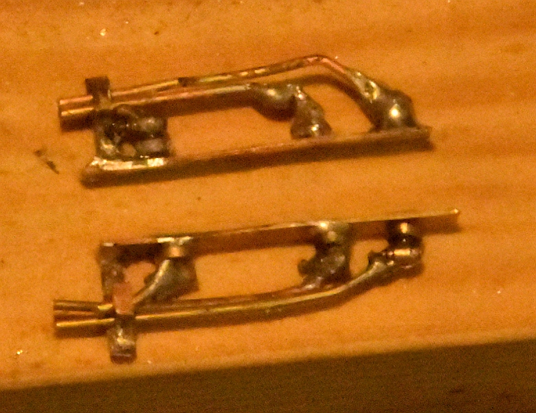
The braking system is the next on the list of to-dos.
Its suggested that a former be created on a piece of wood, (an excellent idea), make sure though that you know which way is up. The back and middle braking frames are different in length as is the connection to the front barking arm. Now when all is done most of this will be painted black and covered in grime so the amount of detail you wish to have is literally down to what it looks lilke when its finished in my book.
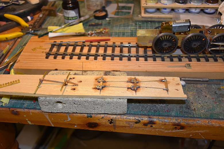
Here it is in its soldered form.
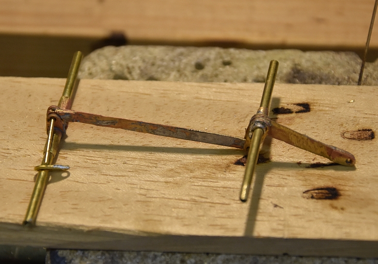
This part is for the front end and connects to a vacuum chamber if you have one.
Connecting up the brake shoes to the main frame is a bit fiddly and the front brake have almost nowhere to go so the arm had to be cut right down.
You can see the frame in place with the brake shoe arms connected.
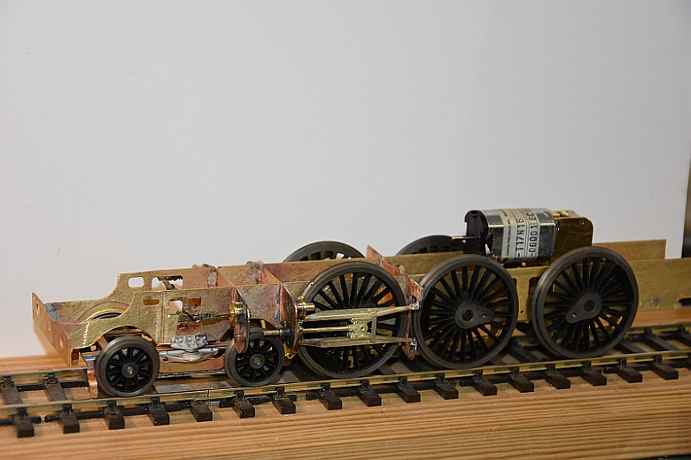
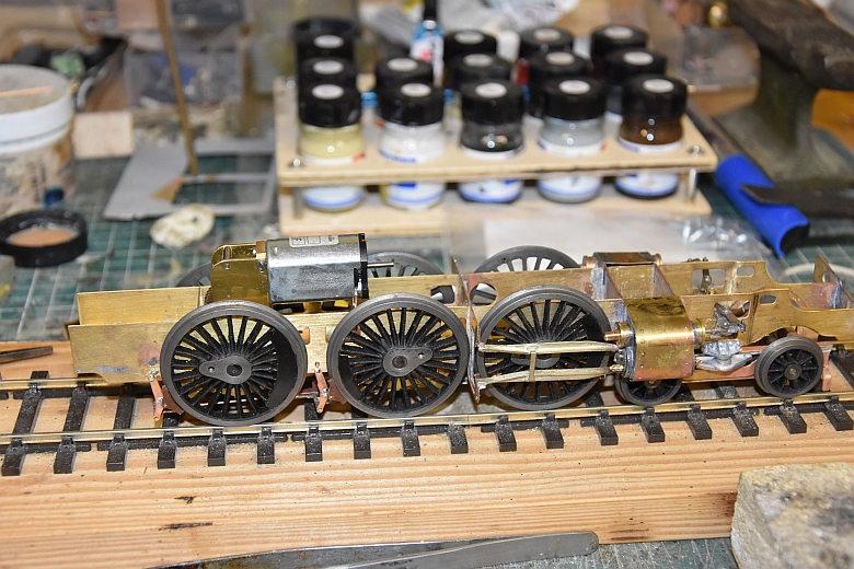
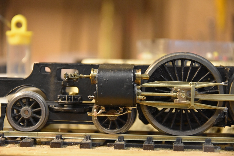
Next job - wheels off and frames given a base spray with UPOL acid#8. Then a couple of coats of Matt Black paint. The same for the front bogie. At this point i'm considering how the wheels will be sprung but want to make sure that the connecting and driving rods fit and work. These are from Premier Components. As this will be an early engine with a later name and number the driving rods will have the connecting knuckle facing forward of the centre wheel.
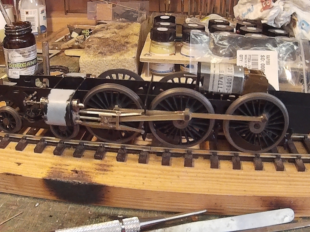
First test with 12v on the motor shows it runs well in reverse and struggles in forward. This is mainly due to the fact the the middle and forward drivers are not yet sprung and slide up and down in their frame holes.
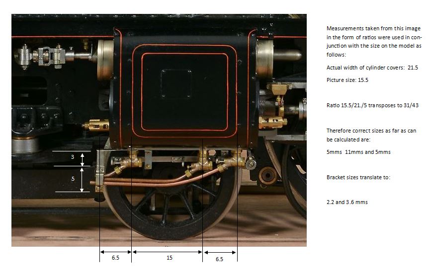
Cylinder drain cocks and piping is to be custom made using Hobbyhorse developments drain cocks and small pieces of brass. The calculations necessary were taken from an example as shown here. Click on the image to see a larger view.
The brackets were made up as follows. two small strips of brass drilled with the same holes as on the cylinder covers above, (not on the etch).
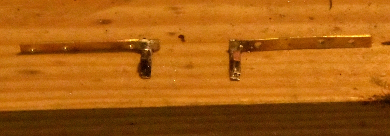
These are the brackets for holding the pipes in place.
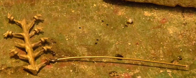
The pipes in the process of being soldered to the drain cocks.
After some trial and error the drain cocks are just about right and ready for fixing to the bottom of the cylinder covers. Probably the most difficult soldering exercise as the parts are so small and difficult to put together.
Here is my end product:
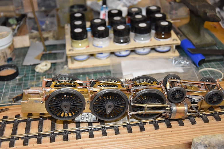
Still the matter of wheel alignment to be sorted out. One centre driving wheel lifts slightly in forward rotation.
The piston guides were slightly askew and needed opening and straightening. This done the wheel movement has improved.