My O Gauge Journal on
Modelling the GWR
A personal Journey
7. Putting it all together
This locomotive will run under DCC. This will be the first occasion that I have used a sound cam to synchronise the chuff rate with the speed of the locomotive. The sound cam comes from EDM Models and is a clip-on for one of the driving axles. It uses a special cam with magnets inserted into it to make the switch send 'pulses' to the decoder.
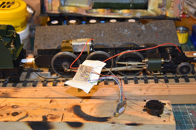
Here is the decoder with loudspeaker attached. It takes current from the rails one half from the uninsulated wheels on the tender the other from the uninsulated wheels on the locomotive. With the decoder positioned with the loudspeaker in the boiler of the locomotive this means that only one wire will be coming from the tender. The only other precaution is to make sure the tender and locomotive are insulated from one another by using a plastic coupling and insuring the floor flap on the loco is insulated underneath as it rests on the tender floor. This is the first time i have used a smaller decoder, (82430). It does come with an 8 pin NRM652 though which I cut off and then solder the wires to a small piece of Ferro-board as shown above. That will need to be insulated before it goes into the boiler as well.
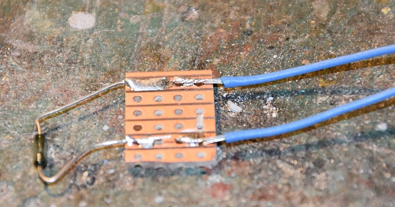
As stated previously I'm going to use a cam magnet to synchronise chuffs this time and here is the reed switch setup on a piece of board to be fixed on the inside of the mainframe. as shown below.
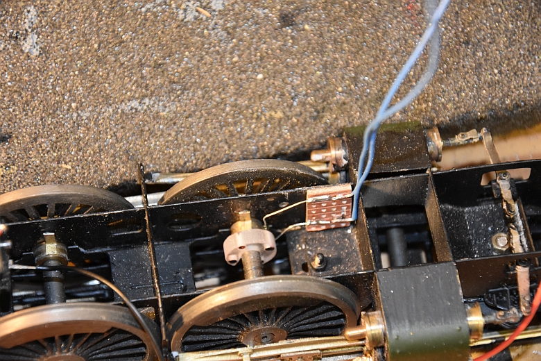
Make sure the reed switch is not touching the cam or the axle on which the cam sits as it is fragile and made of glass. The wiring for all this follows:-
The basic principals that are always the starting points with DCC is that the motor and rails are NOT directly connected. They both have connections on the decoder. Secondly, everything must be insulated so as not to cause short circuits and therefore damage to the decoder. The feed from the rails is AC and not DC and this allows the system to send messages to all the locos that have decoders in them. It means that isolation sections become a thing of the past. That more than one controller can control locos on the same tracks. That one controller can 'steal' control of a loco controlled by another controller if necessary. And then there are the sound effects that can also be controlled by the driver of each locomotive, apart from the automatic sounds that each loco can generate to add realism.
Having cut off the NEM 8 pin socket what next?
The wired connections are as follows:
| Pin | Description | Colour code |
| 1 | motor terminal right | orange |
| 2 | rear light | yellow |
| 3 | function f1 | green |
| 4 | track connection left | black |
| 5 | motor terminal left | gray |
| 6 | headlight | white |
| 7 | common (+pole) | blue |
| 8 | track connection right | red |
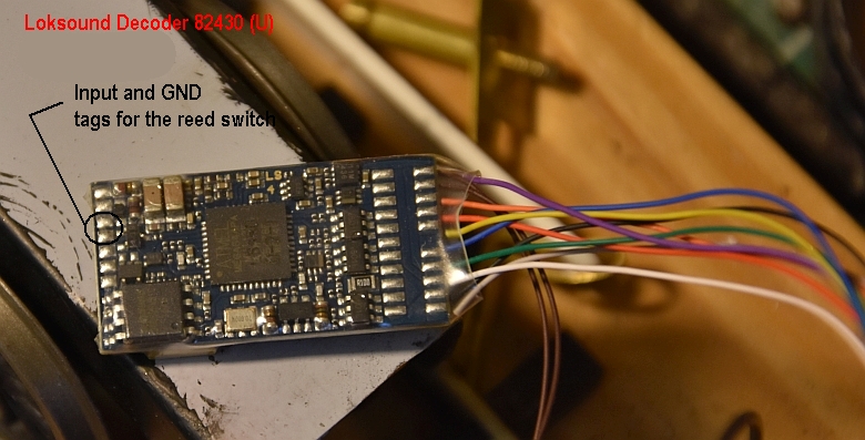
Also be aware that these solder tags are minute and very careful soldering is needed if you are not to make disastrous mistakes!
All decoders come with the loco address set to 3 so this will need to be changed first. I had a gap in the numbering of my locos as one loco is out of commission and so the castle is set to 6. All the settings may now need to be reset to suit the loco and all locos can and do perform differently so some time in the future this will occur. But for now to setup the cam for synchronised chuffing the following needs to be attended to:
Set CV57 to 0 and enter a value >= 1 in CV58. CV58 defines after how many pulses by the sensor the next exhaust will be produced. I keep a diary of all settings for each loco I have made or changed. This is helpful when setting up a new loco as like for like is a good starting point. For the Castle I already have a Grange and will use those settings to see how the castle performs. As I have stated before this is not an exact science and much trialling and altering of values may be necessary.
After much resetting of CVs the above video tells its own story.
Putting it all together
EDM Models
South Western Digital