O Gauge Modelling on the GWR
A personal Journey
Controlling my level crossing gates
The crossing gates problem could not be solved with the current kit so I decided to start again with a different arrangement this time from GFControls. Their PCB is much more sophisticated and can be used to control signals as well. The use of mini servos and digital 'pots' to fine tune the position of the servos is a great improvement and they do not appear to suffer from 'judder'
Unfortunately I almost completely destroyed one of my gates undoing the connections under the baseboard and had to re build it. Fortunately, this has been done successfully. The gates themselves are sturdily build and have brass hinges and brackets. To motorise the gates their hinge bar has to be extended to below the baseboard.
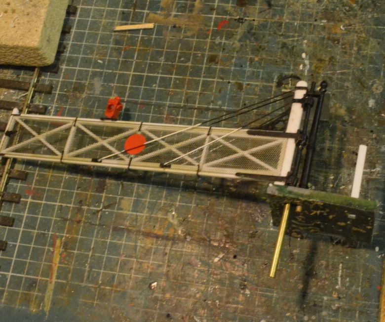
I used brass tube for this and carefully threaded the lower ends to receive 6BA screws to connect the levers contained in the servo kits. This is because i will arrange the servos in 'direct drive' mode right under the bars instead of building a lever arrangement.
However, this will entail making up special brackets to hold the servos in the correct positions.
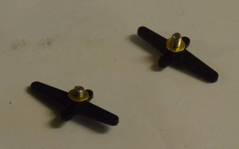
This is how the upper levers will attach to the crossing gate arms.
There will be a small distance between these and the lower arms on the servos and the special brackets i have designed to hold the servo and give clearance to rotate the arms is shown below.
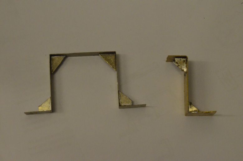
As luck would have it one of the crossing gate rods comes through a support beam for the baseboard and will be a different distance from the other one which will fit directly onto the underside of the baseboard!
I used the levers supplied to attach to the servos, but the ones I used to connect to the tube extensions did not work. AS the holes in the levers were almost the same size as the tube, (the tubes pushed through the soft polystyrene and consequently these levers kept slipping round the tubes. I supplied harder levers with a different diameter hole and these grip the tubes nicely when the screws are tightened up. Below are the brackets holding the servos positioned under the baseboard. the levers on the servos are connected to the levers on the extension tubes by two screws. This allows for some adjustment and can raise the gates for a small amount of floor clearance.
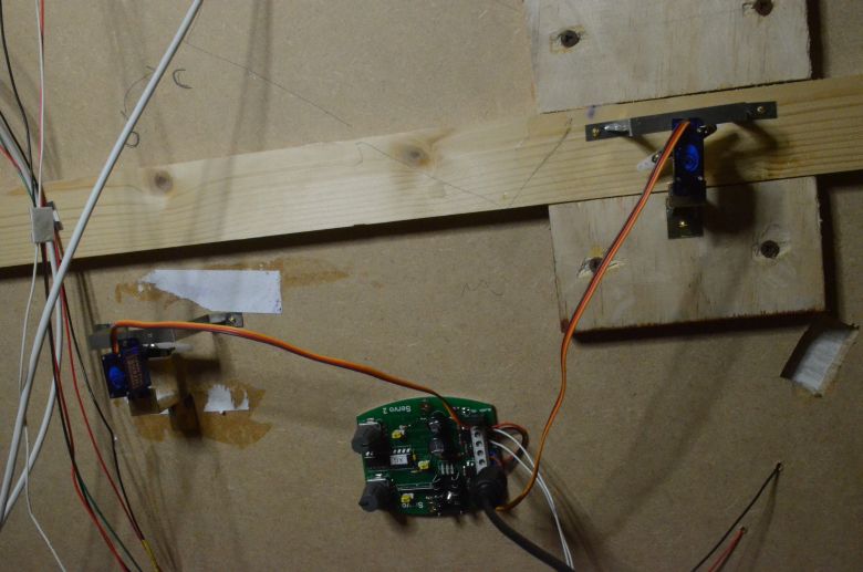
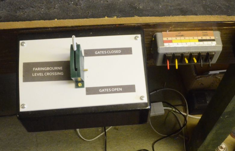
I decided to keep the control PCB near to the servos so screwed it under the baseboard. The control switch is positioned on its own control box as shown below and is a simple Hornby on/off switch.

The gates are now fully working. Its important to make sure that the clearances under the gates are just that and that the gates don't rub on the floor or catch on brackets as this will interfere with the fine tuning and position of the gates. Once this occurs you will have to retune and reposition the gates!
Here is a video of the gates working
One way of solving a couple of issues with the 'floor' of the level crossing was to replace the existing epoxy boarding with real boarding. This has improved the look of the crossing and it now only needs painting.
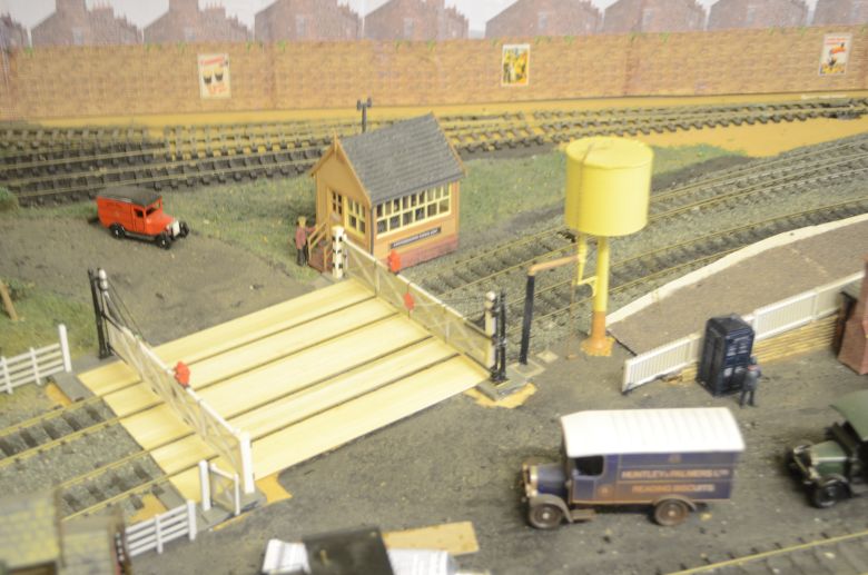
These are strips of lime wood. and although the picture makes it look as if they are single pieces they are indeed made up of strips 7mm wide.
The wood has been painted and the control box given the appropriate lettering.
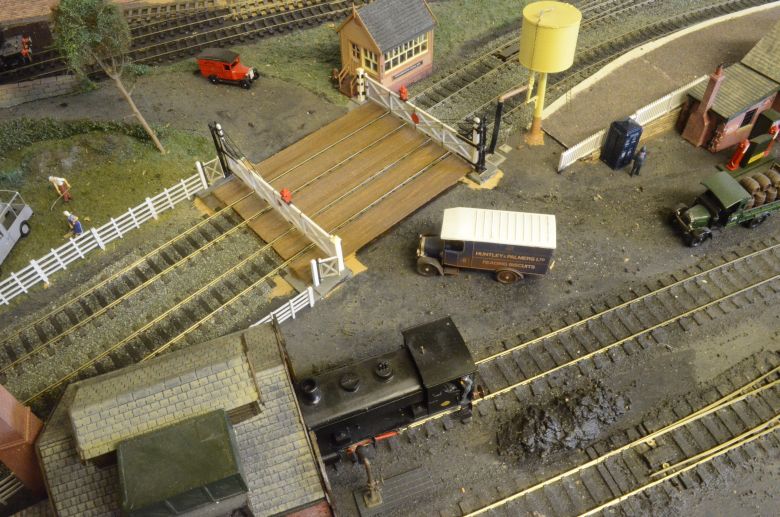
The lettering on the control box gives priority to the railway as far as open and closed is concerned.