O Gauge Modelling on the GWR
A personal Journey
Signalling my railway
Not my favourite subject and not one I want to develop too far down the road prototypically. Here is a rough diagram of what it might develop into, (click the image for a larger version);
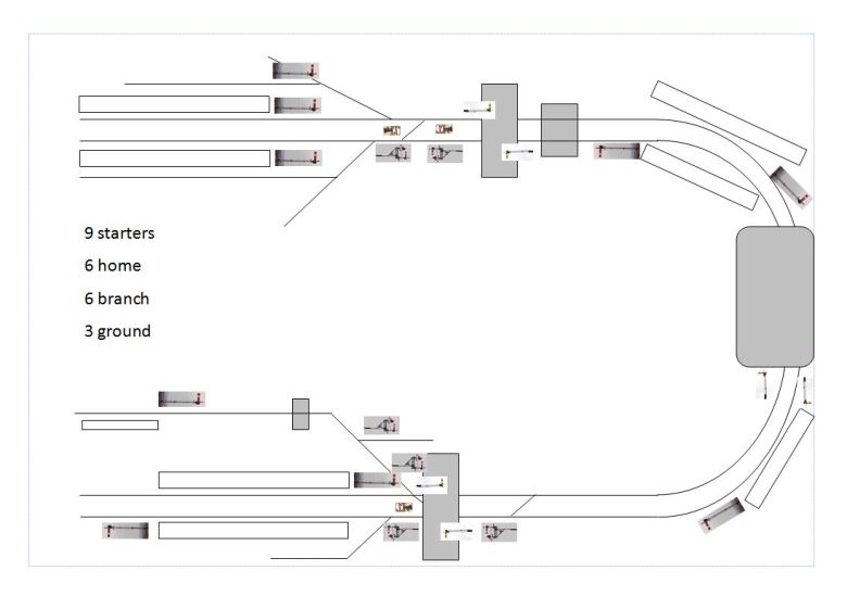
Started on a Home and starting signal and finished off the branch signal. All three are now ready to be wired up and made to work.
Also started two Ground Signals
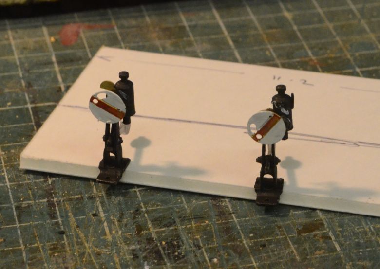
These can be made to work but not a priority for me at this time.
As far as I can tell I will need several starting signals at the ends of each main platform. On some lines there is the need to cross over to up line working from down line working and to facilitate this I will use branching signals. Here is the framework built to create one of these. Eventually this will be a working signal so it is constructed with this in mind.
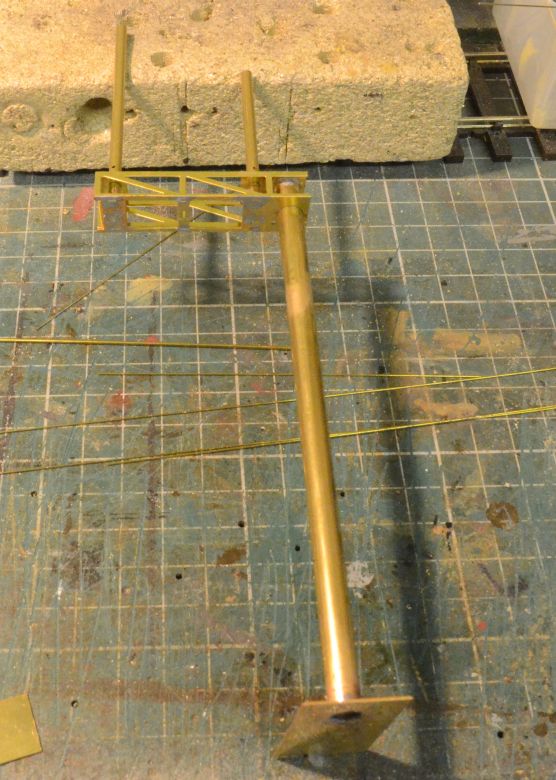
This is a metal post type and to my mind easier to build than the wooden post type. But I will compare the two as it progresses. Here is the structural components assembled ready for washing and primer etching.
Those with a critical eye will notice that the pilot arms have been rearranged as has the base and platforms to conform to GWR practice. My mistake!
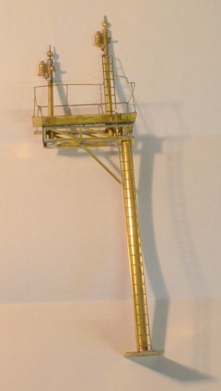
Here is the arrangement with the link arms and rods in place.
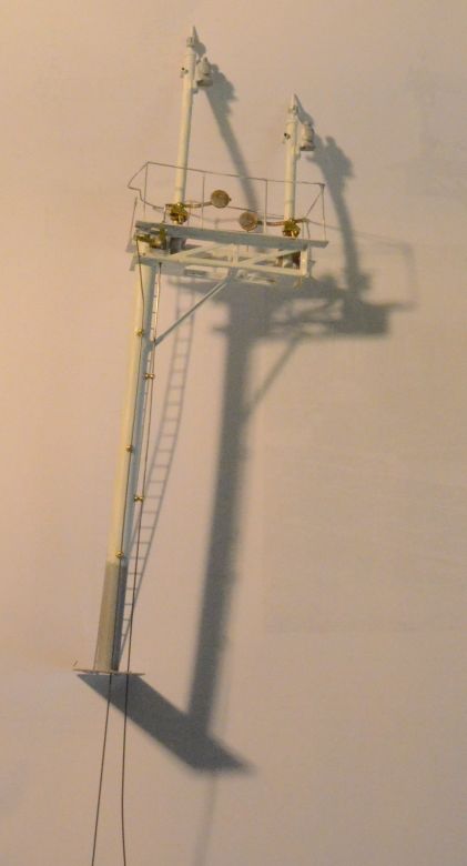
I use piano wire for the control rodding for strength and have drilled the main post to accept hand rail knobs to support the wire rodding. The small ladder was in the wrong place and has been removed. On making another I will leave off the handrails and ladders to the end as it makes it difficult to assemble the rodding guides and levers. painting would also be left until the signal arms are fitted as I have had to scrape off paint in several places where alterations and assembly of small arts was concerned. I'm not convinced that the travel of the rods from the counter weights will be enough to turn the signals enough so that the red and green spectacles will be in the right place. Re the piano wire I normally put a length in my Dremmel and pass it through a small hole in the end of a hammer shaft. This is a neat way of straightening the wire, but be careful as it can whip and cause damage. I hold the shaft at an angle and as the wire rotates I draw it through the hole switching the drill off before it pulls the wire out of the hole. Failure to do this results in the wire distorting.
Here are the ground signals insitu but not working yet Click the image to see a larger view.
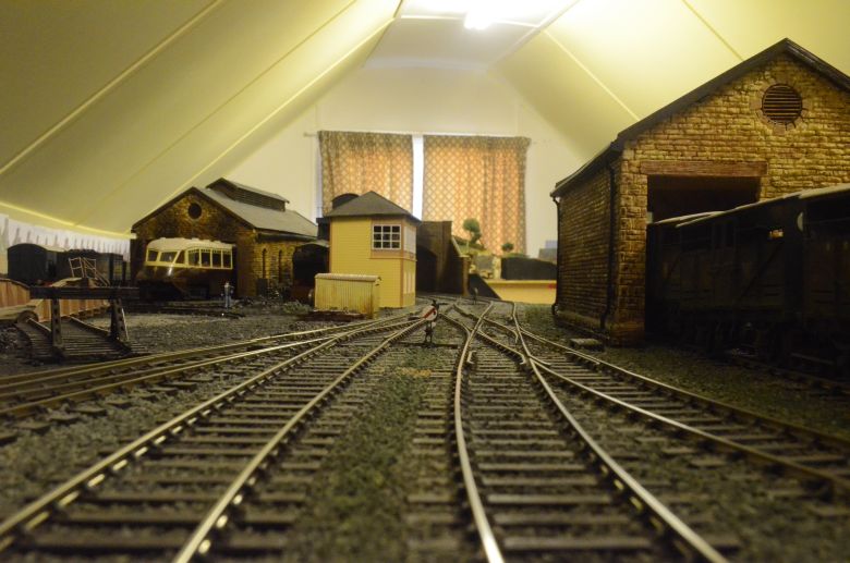
Some 3 weeks later, here are the signals in situ ready for control.
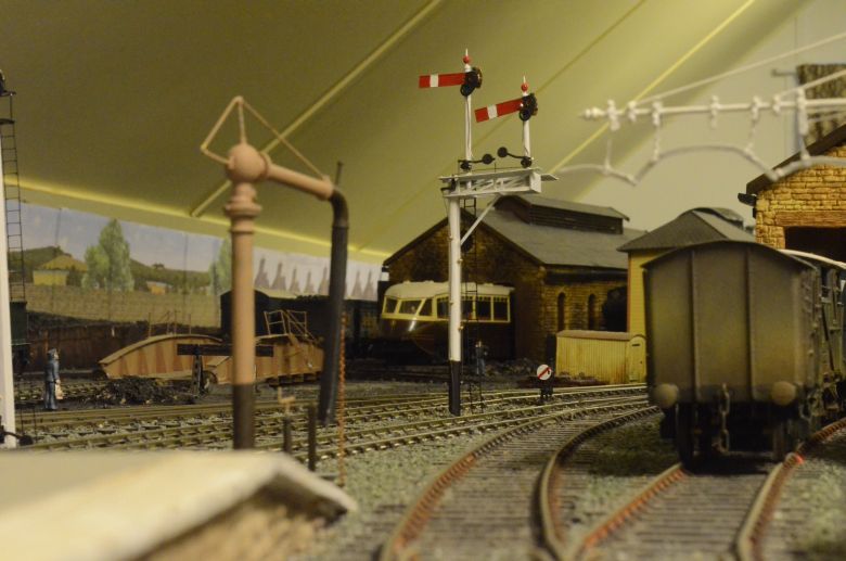
I've lost the safety rail around the platform for now but both levers work. There is little clearance between the pole and passing traffic though, but just enough.
Signals Supplied from:
Model Signal Engineering