O Gauge Modelling on the GWR
A personal Journey
Developing the project into a complete working system
In thinking how I might control all this gear I have started to investigate possibilities and have come up with the following using two signal semaphore kits from Embedded Controls Ltd. Click the image for a larger view.
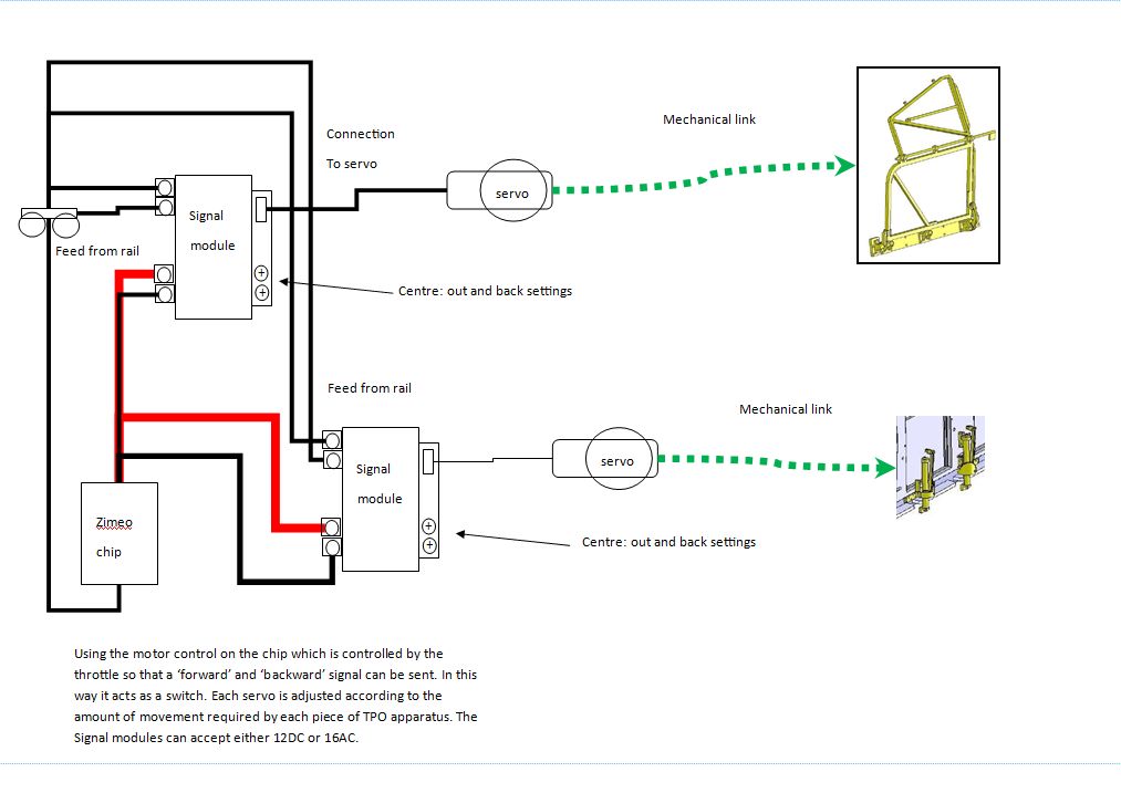
But, as my railway is DCC throughout, there will be a DCC chip inserted into the coach to control everything. Some chips have servo control as part of their 'services' One such chip is the ESU Loksound 4 XL. This particular one can control up to 4 servos. I have also invested in the ESU servos as shown below.
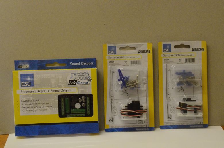
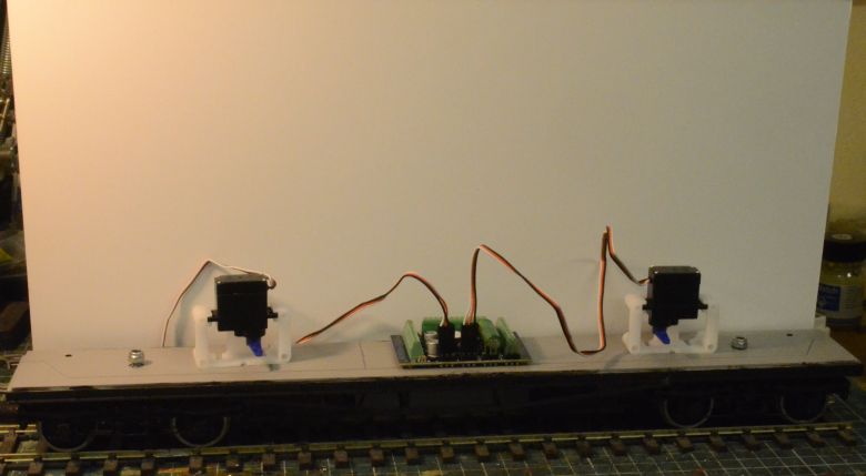
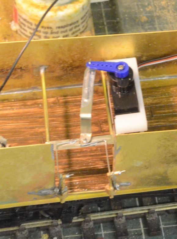
Out of the packing and placed on the chassis this is roughly how they will be positioned. I chose to buy ESU servos as they come with a rather nice holding bracket.
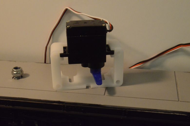
A hard plastic bracket that holds the servo in place with screws and allows it to be positioned a couple of ways.
The revised circuit now looks like this:
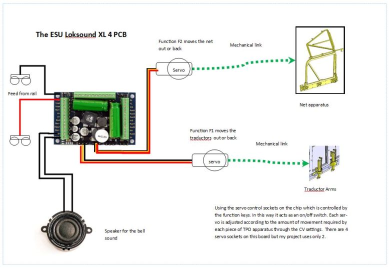
Now for the technical bits:
The way to get these servos working from my control system, (ZTC 505), is as follows:
Set up the servos to work from AUX 7 and AUX 8 on the Loksound 4 XL PCB, (this will use the first two of the four connections on the PCB for servos). You can download the ESU programmer software from their site to do this. The process in the software is as follows; but to do it yourself will require you to have the ESU programmer board:
1.
In Function mapping
set F1 to Aux7 and F2 to Aux8
2.
In Function outputs
select Aux 7 in the output box
3.
At the bottom of the window in the
Output mode (effect) box select servo
4.
Underneath that you can also set the
speed, start position and end position
5.
Repeat 2-4 for Aux 8
There are also a number of changes to make to certain CV settings as follows:
CV31 should be set to 16 , CV32 should be set to 0.
The mode setting for AUX 7 which is CV 323 is 27.
The mode setting
for AUX 8 which is CV 331 is 27
For AUX 7 the
following CVs and settings were applied:
I started with: CV 326 = 10, CV 327 = 0, CV 328 = 36
(setting CV 328 to
36 gives an approximate 90 degree turn and to 18
an approximate 45 degree turn (the range is 0-62).
For AUX 8 the following CVs and settings were applied,
I started with: CV 334 = 5, CV 335 = 0, CV 336 = 50, (336 has been upped to 50 as the net needs a greater traverse than the traductors)
(setting CV 336 to
36 gives an approximate 90 degree turn
and to 18 an approximate 45 degree turn (the range is 0-62).
334 was set to a
faster setting because the net has further to travel than the
traductors.
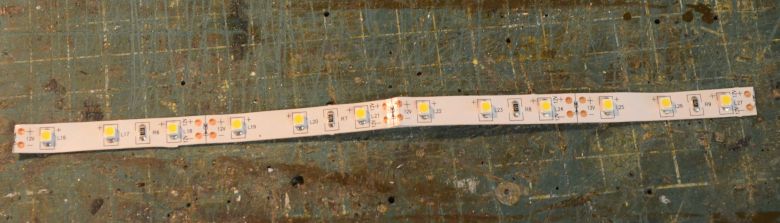
I've put in some LED strip lighting at each end of the coach to illuminate the 'posties' in their working positions. This is an LED strip of three lights with inbuilt resistors from CRT Kits.
All that was necessary was to set up the CV values to make the lights come on using function 3 on the controller. This was done as follows:
To get AUX1 to output to function f3
set CV 31 to 16 and CV32 to 2
Set CV 330 to 4
To alter the brightness of the LEDs
Set CV 31 to 16 and CV 32 to 0
Then set CV 278 to 5 (
Value between 0 & 31, where 31 is the brightest )
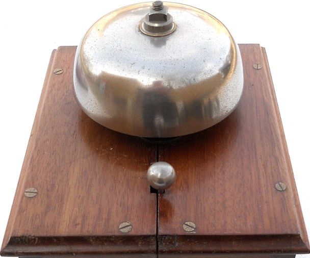
The Warning Bell
All the videos of present day TPOs preserved and otherwise don't seem to have a warning bell, but according to Hosegoods book page 21 it reads as follows:
Once the net was lowered a bell would sound .... inside the coach.
I believe it was a 6" bell that rang continuously....... to warn staff that the net was lowered and that they should keep away from the net door. The bell itself was kept in a locked cupboard and powered by 3 battery cells. It was activated by a contact on the net and could not be turned off or tampered with.
I'm thinking it would look something like this:
![]()
I sent the sound file for the bell to Kevin at Coastal DCC. He edited it for me as it needs to have a 3 part compose. This enables the file to be adjusted and edited as necessary before feeding onto the ESU pcb. To complete the installation i took my coach along and he uploaded the sound file. We then trialled it against the lowering and raising of the net to get the right sync between movement and bell sound. If you want to do this yourself then you will need the programming PCB available from ESU at around £48. The software to drive it is a free download from the ESU web site. One thing to watch: the length of the sound file and the fact that it loops means that it will play for a certain amount of time. This has to be gauged against how long you expect the net to be down so beware!
And here is the coach fully lined and finished off in service on the railway:
>
The Traductor arms update:
I've put a couple of runners across the coach body and replaced the traductor arms so that the springing for the arms also holds the mailbags. here is a mock up;
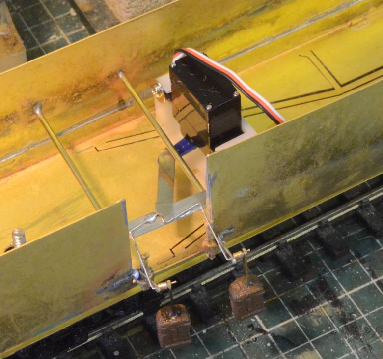
This arrangement will allow the arms to be raised and lowered prior to the bags being collected by the ground net. The movement of the solenoid is only through 45 degrees so that CV value has to be changed, (see above).
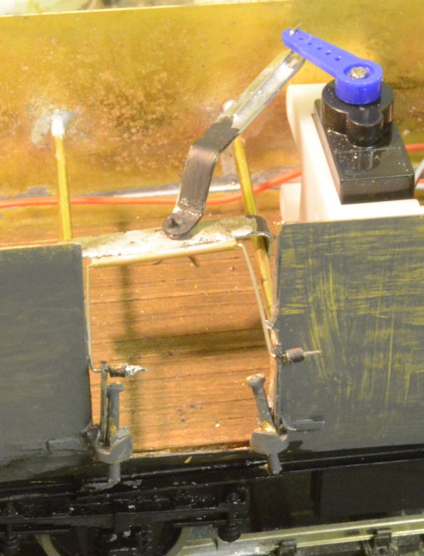
The solenoid is turned upside down and a stronger arm with pivots at both ends made up. This is now strong enough to extend and retract the traductors
The net is now finished and strengthened with chains and 'rope'. Here is a video of the two parts working. This was taken before I had fine tuned the speed:
The traductor arms were not quite horizontal and the ground bags were catching on the traductor arms so I remade the gear in the coach making the control arms a little longer and improving the swivel joint. This solved the problem.