My O Gauge Journal on
Modelling the GWR
A personal Journey
Signal Construction
Step by step: (Click any image to enlarge it.)
|
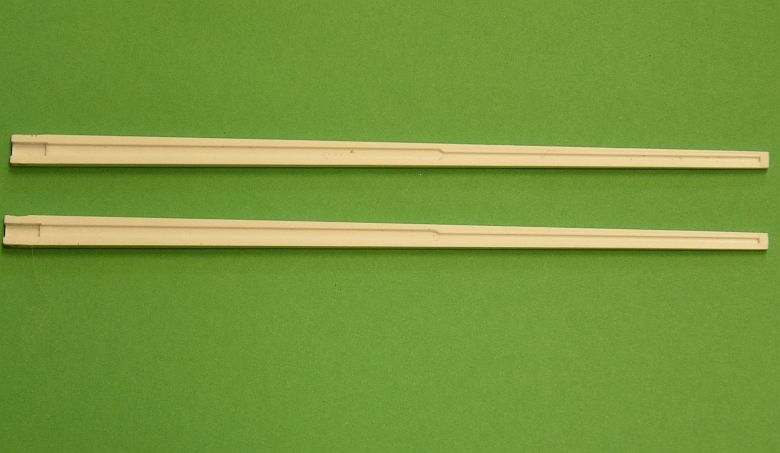
Starting with the post, separate both
halves from their sprue. Keep them separate for now. |
 |
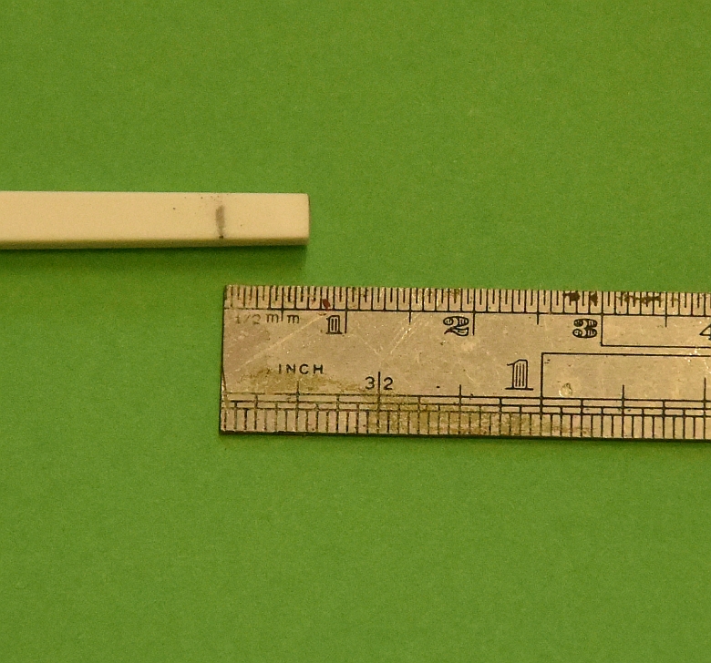
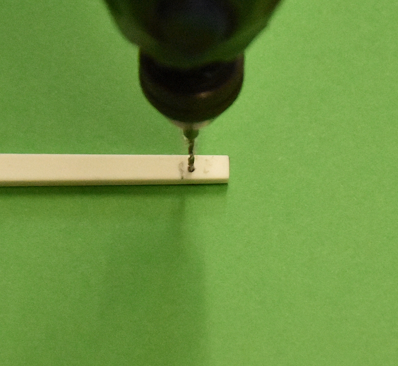
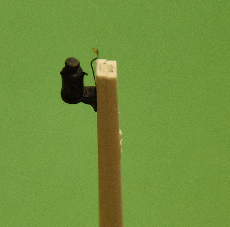
Measure where the lamp bracket will go on one half of the post, (8mm down from the top), and drill a small hole just above that mark for the LED wires to pass through
 |
 |
|
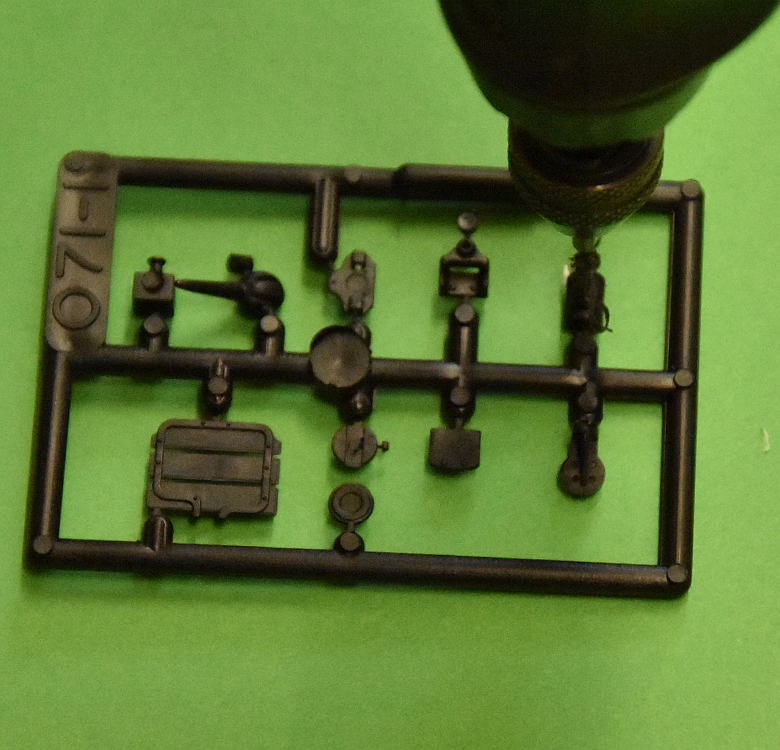
Drill a small hole right through the
lamp whilst it is still on its sprue from the lens side. |
 |
 |
Pass the fine wires of the LED through
the hole in the mast half, (allow for about 15mm to project
out of the hole so it can be fed into the lamp. |
|
Use a contact adhesive and put several
small amounts in the groove of the mast to hold the small
wires in place and give them added protection. As these
wires are not long enough to project out of the bottom of
the mast, solder thin wire (500mm long) to them and secure
in place in the groove, making sure the soldered connections
do not short out on each other in the groove. |
 |
 |
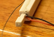
Glue the two halves of the post together using plastic weld. The two wires projecting out of the
bottom of the post will be secured by using the spigot
supplied, but not yet. |
Glue the lamp bracket up against the 8mm mark you made earlier using plastic weld. Also glue the lamp in place on its platform. Once dry you can feed the LED into the hole in the lamp and mould the wires carefully against the lamp body to conceal it. Paint the wires black and use the paint to secure the wiring in place.
 |
 |
|
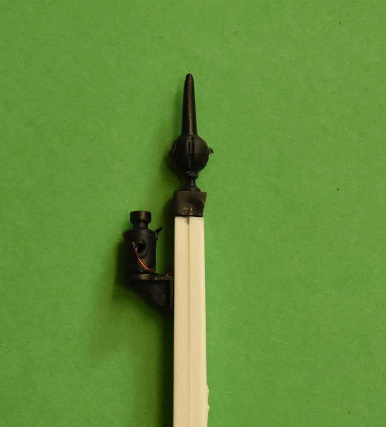
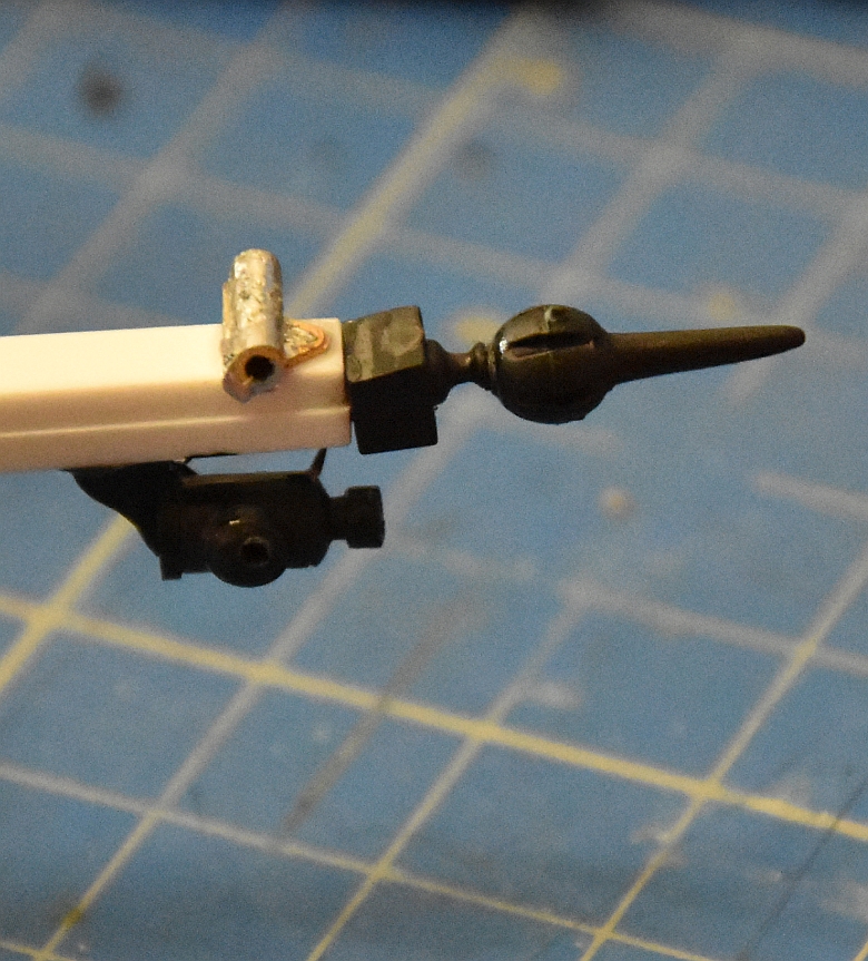
Glue the ball and spike finial together
and fix onto the top of the post. |
 |
|
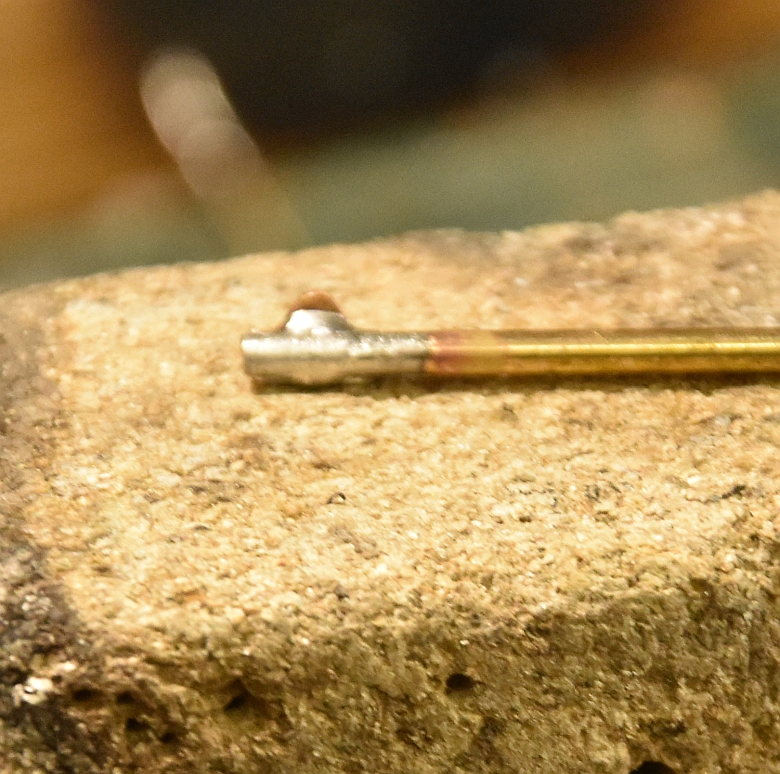
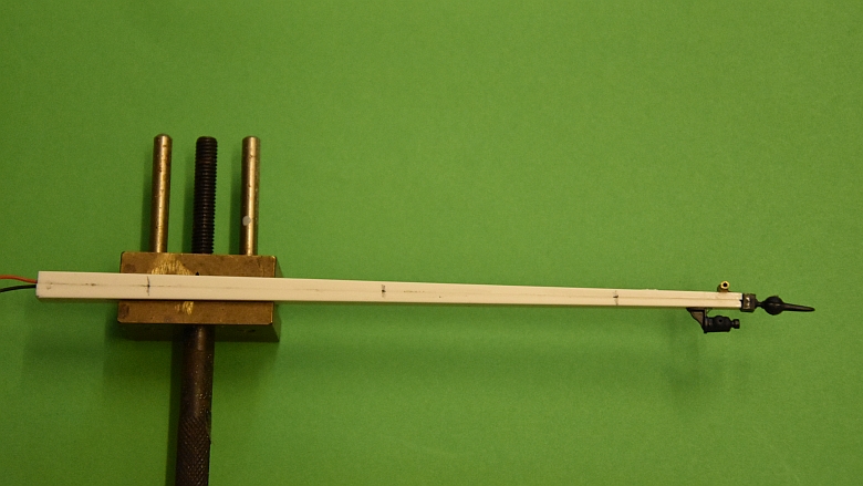
My preference for supporting the arm is to use the brass bracket with a small piece of brass tube soldered to it, but the plastic bracket supplied works just as well although rather fragile. So I solder up the tube and bracket and superglue it on the opposite side to the lamp.
The complete unit can now be screwed together and the baseboard cleared of grit ready to glue the base in place. I used a plastic door for the base, 6cms x 2.5 cms as I have a dozen spare from another project. Having everything together makes life a lot easier and ensures consistent performance of the connections to the signal blade. 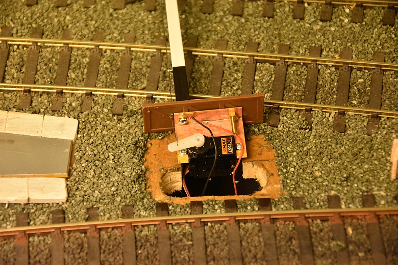 The grit is wetted and then scraped away to reveal the baseboard. Once it has dried a small piece of paper is used to hide the servo and grit can be replaced around the base to finish it off. 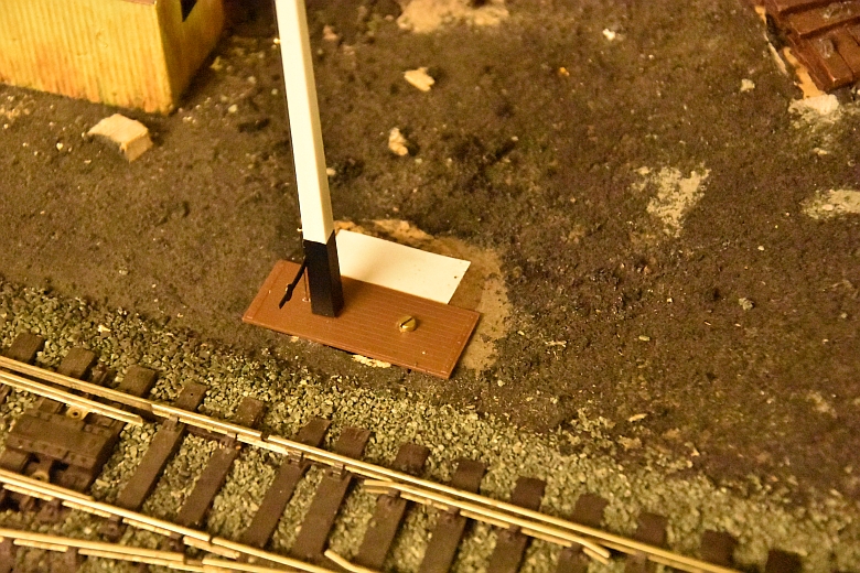 Once set cover the area with fresh grit as shown here and secure with a mixture of PVA and water. 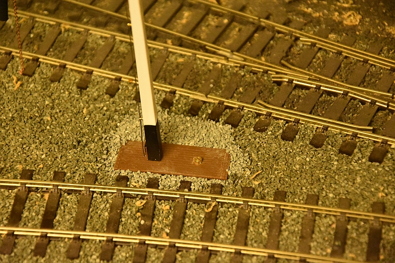 This section of the railway has three working signals. The control panel is made up of a CamdenBoss case 187x 243 x 103 from their 8000 series. There is enough room to have the line indicators and bell along with the switches and signal control boards. here is the inside:- 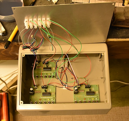 and the outside:-  |

PECO Signals
LK-790 GWR Home or Distant Signal