My O Gauge Journal on
Modelling the GWR
A personal Journey
Creating the control boxes
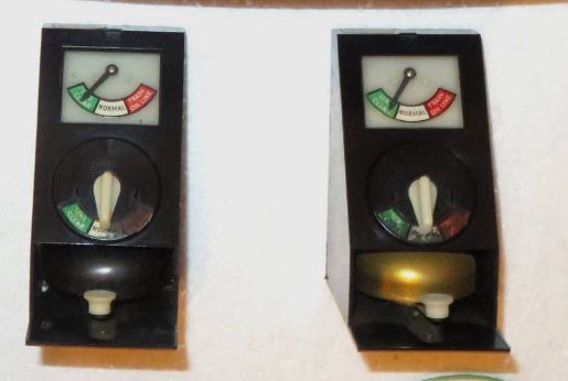
The traditional control of rail movements by signal boxes was by a system of block signalling using electro-magnet circuits to indicate train positions. I believed it would be possible to use servos and signalling apparatus to imitate this system. So much so that it could be put to use on any size and gauge of railway. The only time this has been attempted in the UK is by Triang as shown below and only as an indicator and bell communicator system.
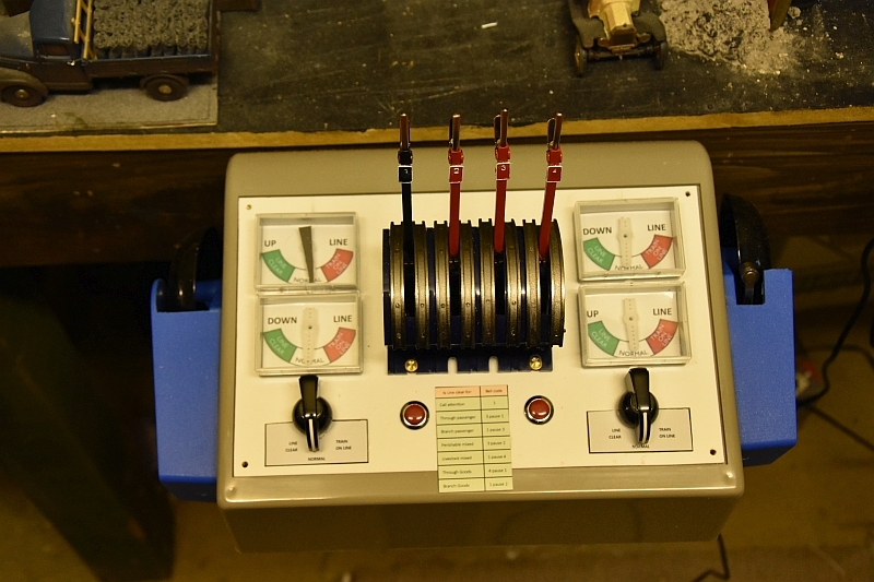
My design would incorporate all the components of switching signals, controlling signals and communicating between sections of the railway under one roof as per a signal box and look something like the diagram below. This is just a mock-up for illustrative purposes and the dials are not in the correct positions for UP and Down indication at the moment. But it gives a feel of the layout.

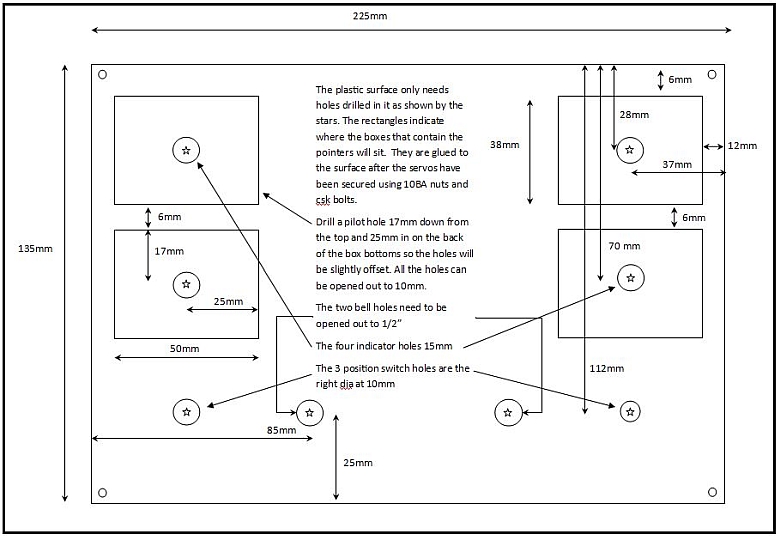
The layout for the holes to be drilled is as follows, (click any image to enlarge):
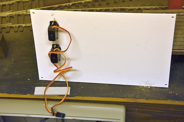
The servos are bolted into place using csk bolts, (the indicator boxes will be stuck over them).
As viewed from the outside this time. A large hole is necessary to accomodate the gearing of the servo.
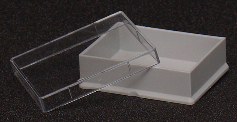
For the indicator panels i used specimen boxes available from Watkins and Doncaster.
Drill a hole in the base and fit over the servo hole as shown here.
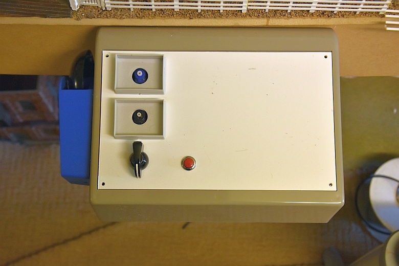
The bell button and three way switch are also fitted at the same time.
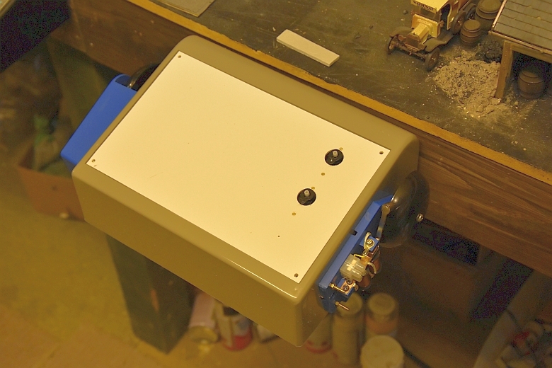
The double control box looks like this:
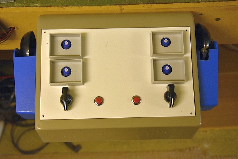
Finally the signal lever switches are fitted and wires fed through into the box.
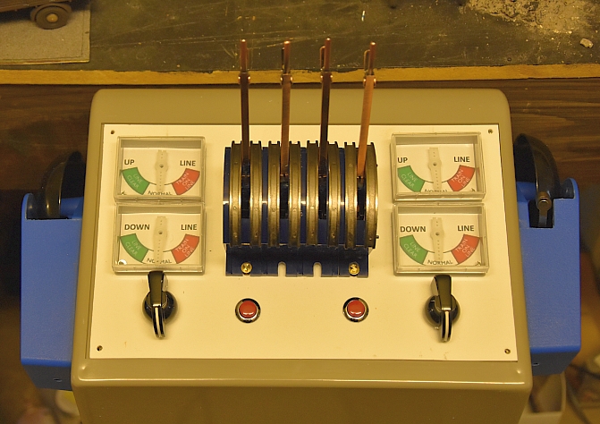
A couple of last bits and pieces, (painting the levers and adding numbers, adding a bell code list, adding a 3 position switch label). But still 3 black pointers for the indicators!
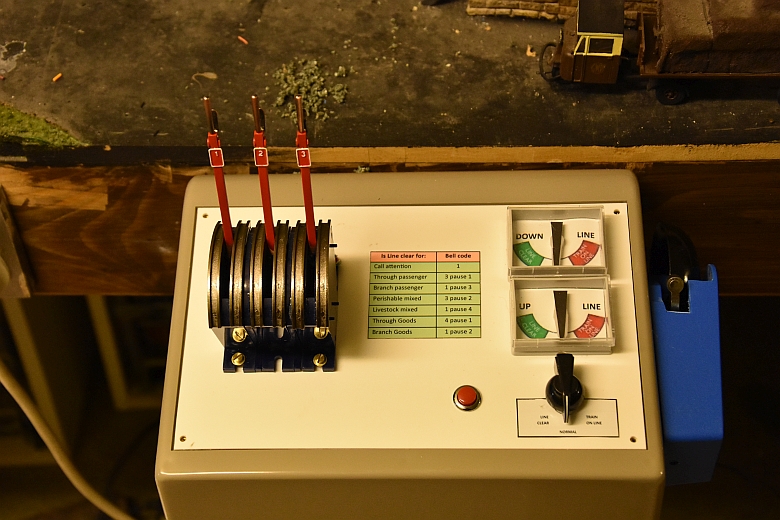
and the end box:-
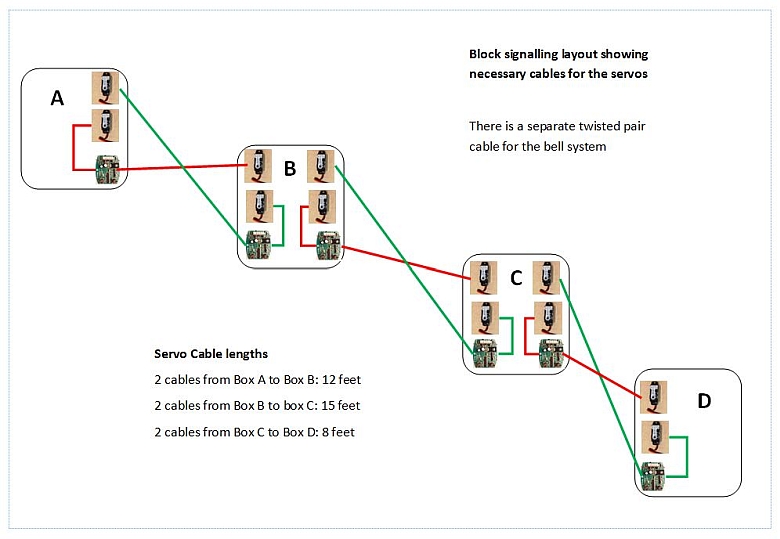
As far as the cable connections and PCBs are concerned this is how they connect together:-
Control Box items:
Rapid Electronics