My O Gauge Journal on
Modelling the GWR
A personal Journey
Motorising the tippler
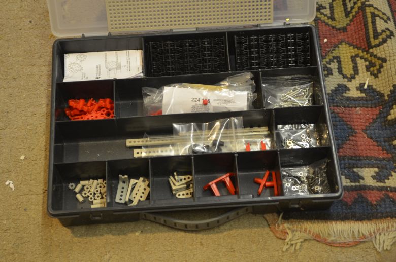
Based on the layout of the Meccano document I have purchased a number of Tamiya brackets, shafts sprocket and chain sets, motor and gearbox sets and worm screws and cogs from Pages of Tools, (see links top right of this page) .
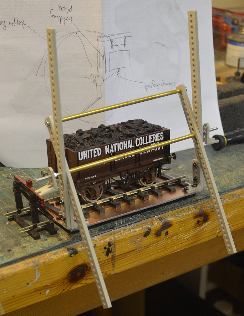
Below is an early mockup of the cradle for the wagon. I have put a wagon locking beam on the main axle. The idea is that as the wagon platform rotates upwards and in a clockwise manner so the locking beam will bear down on the wagon to hold it steady while it continues to be rotated and empty its contents into a hopper below. A backplate will be needed to stop the wagon moving against the main axle.
Here is the compiled model in styrene and wood with brass shafts and bearings. How this came about is accessed by clicking here.
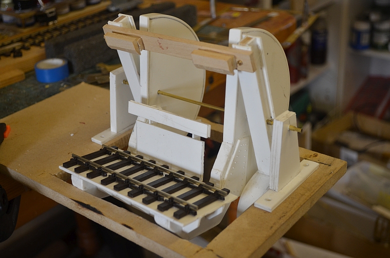
To drive this arrangement I will put flexible racks on the large semicircular counter balances and drive them with a worm gear arrangement.
Here is a mock-up of the arrangement:- click for a larger view
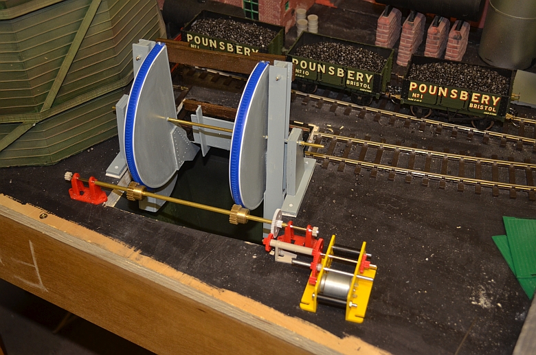
The flexible rack has been fixed to the tippler with a small screw at each end of the track, (its a shame they are bright blue!). Once the position is seen to be accurate I will glue it in place and paint them grey.
Both the track and the brass gears rotating the track are from Motionco. The electric motor kit and plastic gearing are from Technobots. As a loose fit it appears to work. the motor will be hidden by a small building but this will be fitted after the main building for the tippler has been put together and built around the tippler lifting mechanism. Squaring up the track on the platform with the track leading up to it is also crucial. As the tippler track rotates, the inside line must not be any higher than the lead-in track or the wagons will tend to derail easily. Therefore getting the height of the rotating axle right is very important. And yes there were alignment issues as the lifting arms were a little out of true. So to get around this I made flexible axle supports for the driving gear as shown here:
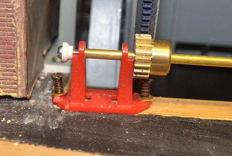
Theses were made up of a spring resting on a washer as shown as the track arms rotated and moved out of true the supports also moved maintaining the right aboumt of adhesion. The right hand support only had one screw to hold it in place as shown here:
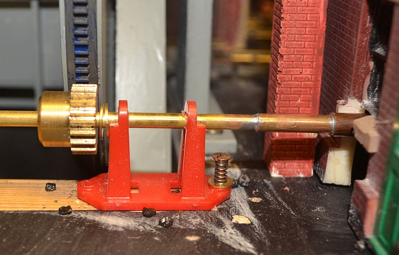
Sometimes the simplest of solutions are the best!
By now i have replaced the motor and gears with a stepper motor to be driven by an Arduino Uno board which will require a bit of programming, (more on that in the other sections on this project).