My O Gauge Journal on
Modelling the GWR
A personal Journey
Slip Coaches
This project will utilise DCC in controlling a coach that can be slipped at one of my stations. Currently investigating how the control of this coach will be undertaken and the methods in place to detach it from a train.
Duck and the Slip Coaches - UK - HD by tttepisodes18
The above video shows how successful this could be in practice and of course what happens when in the wrong hands! Why is this here, well I can't find any actual video of slip coach workings and this does show what happened to some extent!
AND.... we now have the last coach to be slipped on film thanks to Youtube.
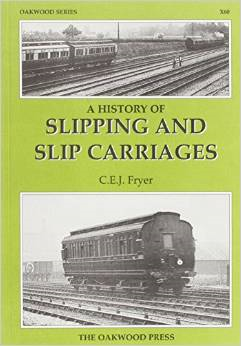
But my starting point was to identify a coach from from C.E.J. Fryer's book. Click the image for a larger view.
.jpg)
Here is the coach as produced by Comet Models in 4mm, but the drawing is of importance whatever scale you build in. Beneath the chassis are 5 cylinders providing vacuum for the brakes on the coach. Click the image for a larger view.
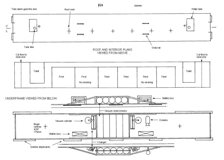
On this option, the slip coach has a guards area at each end of the coach. This enabled the coach to be used in either direction without being turned. The GWR had in excess of 70 slip coaches working before WW1. But during the war they were discontinued. After the war they resumed but in much reduced numbers. There was always the risk of accident as only the guard could control the coach or coaches once they had been slipped from the engine. The process was as follows: the coach would be uncoupled from the main train shortly before reaching its station. The guard would then have control over the brakes and bring it to a stop at the platform whilst the rest of the train sped on. Once the passengers had alighted, the coach would then either be moved to a siding awaiting connection to an arriving train or coupled up to a waiting train, so that it could continue its journey to its final destination.
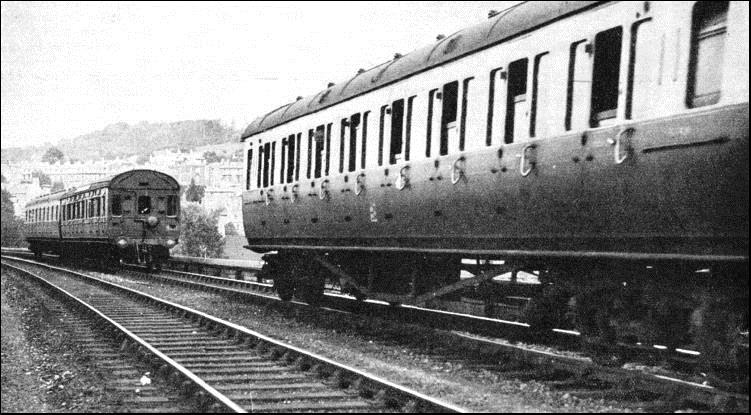
Here is a 2 coach slip in the process of rolling into the station behind its speeding train.
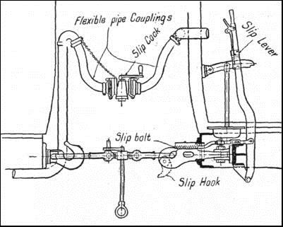
This diagram shows the arrangement of the slip bolt and hook. The lever controls the opening and closing of the hook that will release the coupling bolt. The vacuum pipe has a special valve arrangement that allows it to 'snap' apart at the same time. On the Great Western slip coaches; when a carriage is slipped and the hoses come apart, a spring-operated automatic valve comes into action and seals the apertures, preventing air from getting in and applying the brakes.
One handle does all the work. To slip the coach, or portion of the train, the guard pulls the lever right back to the "slip and brake on" position. This applies the vacuum brake on the slip portion, and releases the coupling and hoses, which are automatically sealed by spring valves as the pipes separate. He then puts the lever back to the "brake released" position, which puts the train pipe in communication with the vacuum reservoir under the coach. The coach then coasts into the platform, where a further movement of the lever to "brake on" brings it to rest.
It is necessary to identify the slip portions of trains in a visible way just as the last coach of a train has its lamp to show the train is complete to signal men etc. At the rear end of the slip, the coach has two lamps side by side, one red and the other white, encircled by red and white disks for daytime use. If two slips are run on the same train, the inner one carries this distinctive tail signal, but the outer one carries the lamps one above the other.
The project now breaks into further sections:
The Slip Coach 1: Uncoupling and braking systems
The Slip Coach 2: DCC control of the coach
The Slip Coach 3: Building the body
Book list: