O Gauge Modelling on the GWR
A personal Journey
Upgrading Turnout control with new switches and control boards
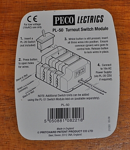
In a previous upgrade I made two improvements. Replacing basic PECO switches with micro switches on all turnouots and building simple control panels with red LEDs to show the path selected. Click here to see what that entailed. The next job is to upgrade the switch blocks and rewire the points into the control panels. To make wiring easier to manage I chose the more expensive PECO turnout switch modules. These are so easy to use and do not require soldering, common earths, etc merely connecting three wires to each switch using the press/grab connectors on the switch casing.
Starting with Wallington Park including the new layout in the sidings next to the creamery and the PO sidings in the creamery itself, it has 14 turnouts.
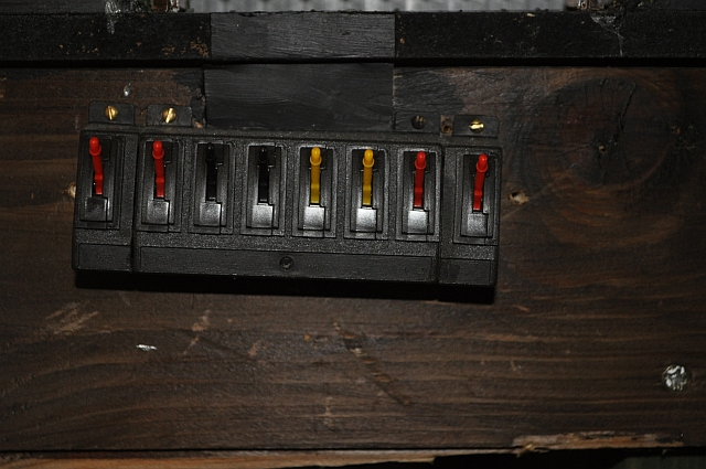
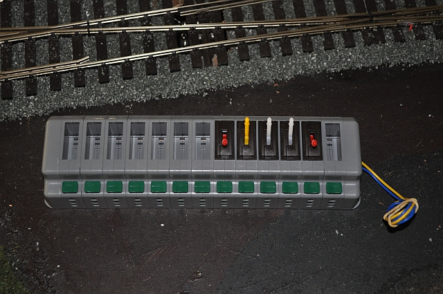
The old switching system with just 8 turnout switches is shown on the left. A bit of fiddling under the bonnet is required to get the switches to work as a bank. In other words a common return is required and this means snaking wires across all turnouts and then making up a common lead to all the switches. Not easy in cramped conditions. With the new system each turnout is wired separately and this makes it easier to setup. More wire admittedly but easier to manage. The three wires from each turnout are grabbed using the green button at the bottom of each switch holder. Power to all the turnouts is provided by the two feed wires on the side of the switch block. If anything goes wrong with the switches they can be easily replaced without the need to undo or re-solder anything.
 |
 |
 |
You can see here how the system works. The only difference appearance wise is that the wires all come in underneath the switches whereas I was able to hide wiring underneath the switches in the old system. I consider this to be an advantage though as it makes it easier to sort out any issues or to modify the arrangement at a later date if necessary. The old system does not do this. You can see from above that I'm increasing the switch control from 8 to 14 for this section of the layout. |
The new layout will require additions to the consul and also a fresh look at switch colour coding.
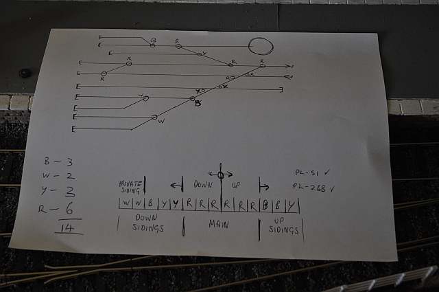
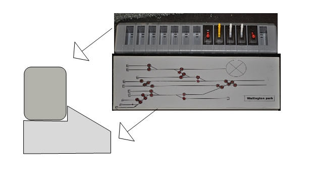
Here is the new switch diagram. The top diagram shows the turnouts
and suggested colour coding of the switches. The bottom diagram shows
how the switches are to be arranged. The issue now is how to connect the
three items together, viz: turnout, switch, consul LED. The colour
coding is as follows:
Mainline turnouts - RED switch handles
Siding turnouts - primary YELLOW and secondary BLACK
PO turnout - WHITE
 |
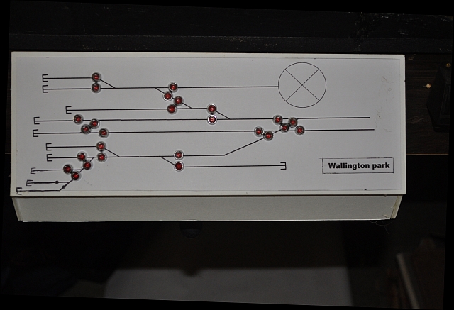
Here is the modified consul. Extra LEDs have been inserted in the bottom left hand corner, but the creamery turnout, ( there is only one turnout, not two as shown in the diagram above), is left blank even though it has a switch to operate it.
 |
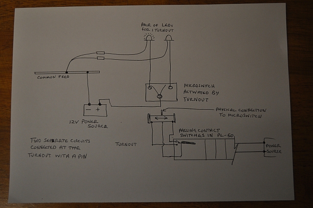
The two sections although together are quite separate electrically. The connection is made through a pin controlled by the turnout solenoid. Again more wire is necessary to complete the wiring but testing and maintenance is now much easier. The micro switch sits on top of the solenoid under the turnout. Actually its a double micro switch but the other switch controls polarity of the turnout blades. This I have detailed elsewhere.
 |
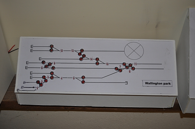
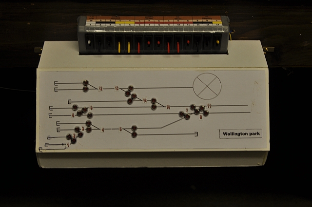
Two points to help with control. You need some kind of coding system to connect the turnout levers with the control panel. Here I have numbered and selected the lever colours as stated above. Each of the five 'sections' is labelled, UP MAIN, DOWN MAIN, UP SIDINGS, DOWN SIDINGS, PRIVATE OWNER SIDING and given a number that corresponds to numbering on the control panel, (see below). I now find I need 14 switches not the 13 shown here and I've altered the colouring to correctly support all the turnouts in this section of track. The private owner turnout in the creamery does not have lights on the control panel as in theory this would be controlled by them but to make life easier for the controller it has a switch!
 |
I have now numbered the control panel lights to correspond to the numbering of the turnout switches. Each pair of LEDs will be wired to the 'other' micro switch underneath its respective turnout solenoid. This system I will use on the rest of the layout
 |
All the switch blocks are now in place. There are some issues with
the passing contact switches fitting into the PL-50 as there is a
tendency to bend a contact if not careful. Also you don't need a
separate common feed for each switch they can be shared thereby reducing
the wiring under the layout significantly as shown here. All Up
sections are designated clockwise on the
layout and Down anticlockwise for
clarity.
Some adjustments to the labelling was necessary to stay within the
specifications of Down and Up and also in directional order as well.
I will be inserting a CDU for testing as some of the turnouts are a long
way from the 16v source. I am awaiting a Hornby unit if successful i
will use two to supply a kick to both sides of the layout. Currently i
have a 16v unit split between each side with a separate output for each
side. I used lighting cable to supply power to the switch blocks. After
testing all switches now work but one turnout at the end of the 'run'
needs a belt to get it working hence the use of a Capacitor
Discharge Unit.
The lighting panels will be setup as they run on a separate circuit and
feed of the second microswitch beneath each turnout. Thats another
difficult boring job i will get around to!
 |
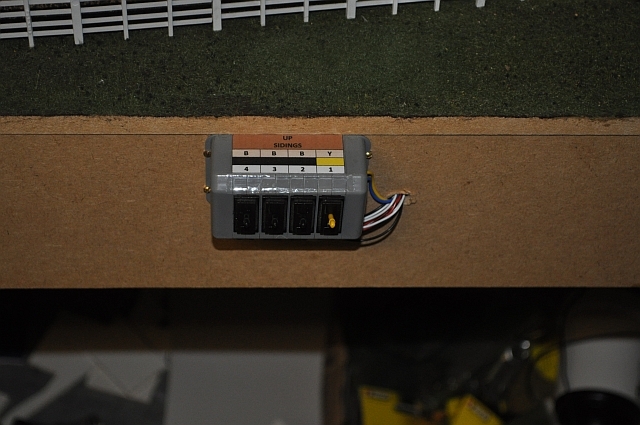 Staverford sidings section switch system |
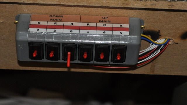 Longhampton Bridge main up and down section switch system |
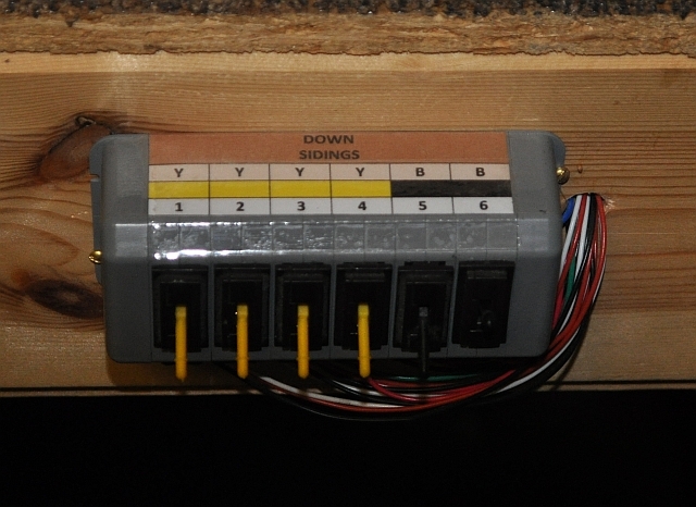 Longhampton Bridge sidings section switch system |
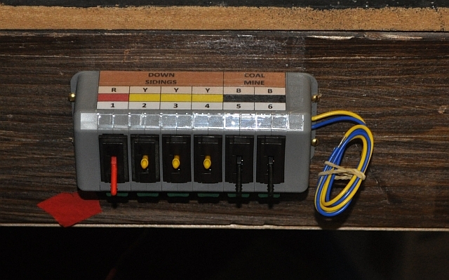 Faringbourne Hill up with sidings and coalmine section switch system. |
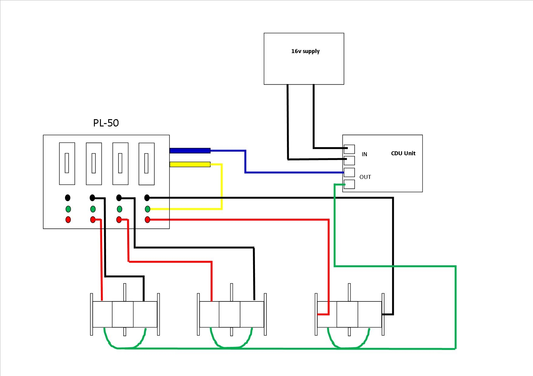
If you wish to use a CDU, (Capacitor Discharge Unit), with this
setup, ( PL-50), then some changes to the wiring will be necessary.
Click on the diagram here to see a larger version of the wiring diagram.
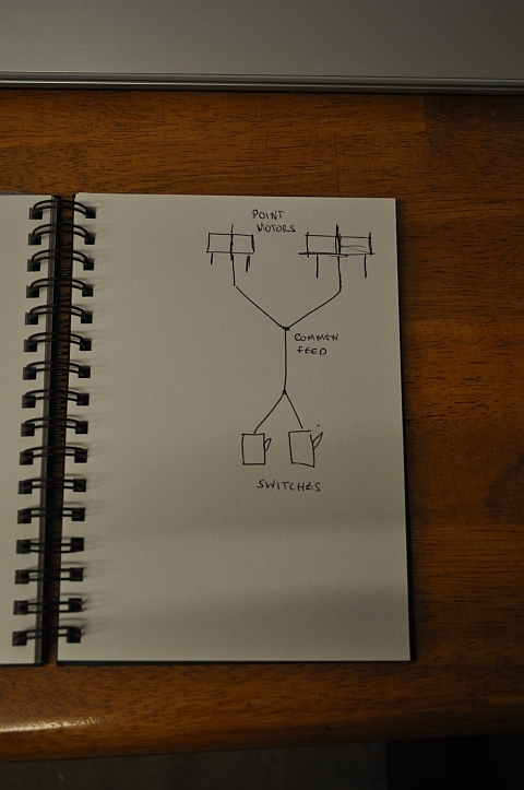
What's important is to realise that the green inputs on this system are
a common feed, so it isn't necessary to have a wire from each turnout
going to its respective switch. you can join all the common feeds
together and have just one inserted.
Make sure the feed wires, (Blue and Yellow), to the switch bank are
split and rerouted so that the Blue wire feeds into the first
Output terminal of the CDU and the Yellow wire, is pushed into
one of the green inputs on the PL-50. All the common feeds from the
turnout solenoids are joined together and fed into the second
Output terminal on the CDU. Finally connect the supply into the
two Input terminals on the CDU. You may have to reverse
them if using DC. There is often a cut-out on the power supply so that
if the connection is the wrong way round it clicks out and nothing
works.
 |
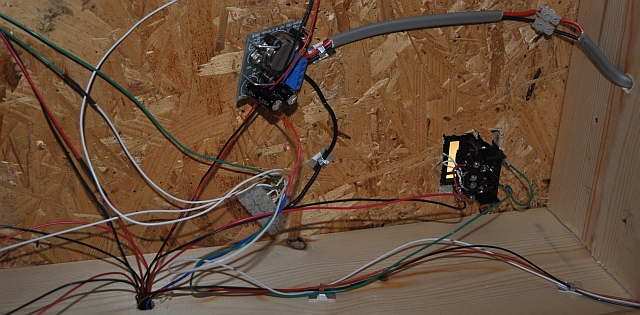
A rather jumbled assembly of the component parts under the baseboard. I've left the CDU 'hanging' as it gives plenty of clearance for air cooling of the circuits although I'm told by the supplier that it isn't necessary. (click the picture for a larger version).
 |
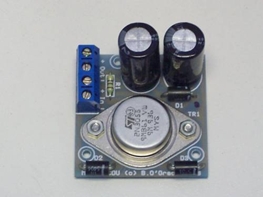 The CDU is powered from a 16v AC supply that has two outputs. I split the outputs between each side of my layout and each section has its own CDU. as they cost under £10 each and are the type that has a large heat-sinked transistor they are extremely reliable and work to order! |
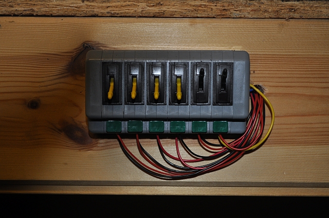
| And the changes to the switch board. the common feed to each switch is gone and the yellow feed positioned into the first green common. Now only two feeds from each point motor are necessary. The difference in operation is that the points now 'click' over more effectively rather than 'buzz' with less power, (I use a 16v AC feed). On the basis that this is a total success all the other switch banks will be converted in a similar way. |
 |
 This is how the combined panels will fit together. They work separately but are activated from a pair of micro switches connected underneath each turnout. |
 Here is the largest panel for Wallington Park section completed. The LEDs now just need wiring up - a major undertaking! |
BUT, I have dumped these as there are issues with fixing the flimsey consul to the side of the baseboards therefore i have moved on. Click here to see how i upgraded.
Modifying the electric switch system
includes the use of 4 CDUs.