My O Gauge Journal on
Modelling the GWR
A personal Journey
Bradley Manor 78xx 2-6-0
This is my second Warren Shephard kit. Chassis build below.
Click Here for body details
Click here for Tender details.
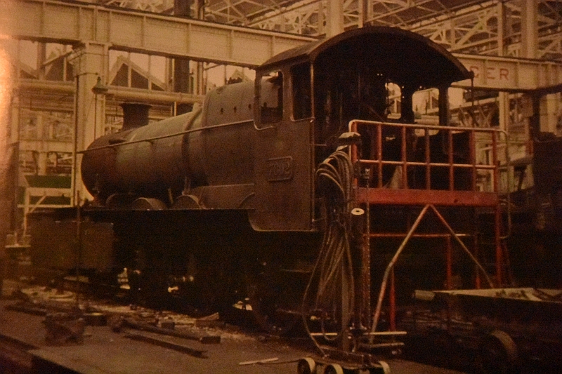
Bradley Manor was the last engine to have a
full service in Swindon Works in 1964. Little did it expect to be
saved from the scrap heap and be preserved to run services on the
Llangollen Railway in the 90s. Not in good condition here it is
during its service in Swindon works:
Prep work
Paint the cast iron wheel sets with black
paint. This includes tender wheels and bogie and driving wheels, (I
used weathered black).
Make sure
all the rivet detail is
completed on the separate etches. The included drawings that Warren
does can be stuck onto the relevant pieces to add rivet detail where
they are not identified on the etches themselves.
I use a Metalsmith riveting tool to add detail
of the rivet heads.
Working on the chassis
Starting with the running frames:
Locate the parts to build the chassis sides and ends, (8 pieces
in total).
Add the cylinder covers and valve ends, (used
superglue).
Wash the chassis built so far in Flash to
remove solder flux residue.
While awaiting the horn blocks, I set about building the bogie for the Manor. There is a little ‘sandwiching’ of parts to be done in the wheel bearing area, but with the use of a blow torch as well as the soldering iron this is not too difficult. I used a screwdriver set to hold all the parts in the correct place during soldering. Check the free play of the wheel sets after building and carefully hone out the holes if necessary. There appeared not to be any ‘cow catcher’ irons included in the frets so I made some up from sprue.
To complete the chassis build. I started to match up the horn blocks once they had arrived. As mentioned before, Slaters now do a cast horn block inner support which is much better than the old folded brass frame they used to supply. I use an axle alignment tool to set up the wheel axles. The slots that hold the bearings etc need to be widened and increased in depth. Care is needed in maintaining the ‘squareness’ of everything, and this can be achieved using the connecting rods as well. Once this is done the horn blocks can be soldered in place. Slaters horn block kit comes with cast guides and springs etc. A fiddly but essential job, that keeps the wheels connected on uneven track
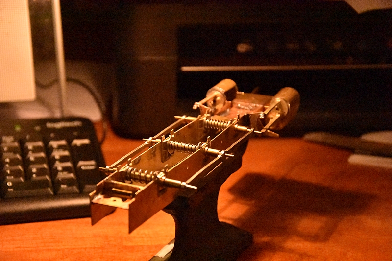
Fitting the Slaters Horn block assemblies is a little fiddly. A small spring sits on the pin sticking up on the cast frame. A retaining plate then sits on top of the spring to keep it in place. Finally the wheel bearing slides onto the guides and sits on top of the retaining plate, completing the ‘sandwich’. A holding bar is then , (in my case), soldered across the bearing bracket to hold everything in place. This gives enough support for the axle bearing to slide up and down and cover any uneven track when the loco is running. All six bearings
are treated in the same way.
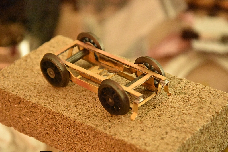
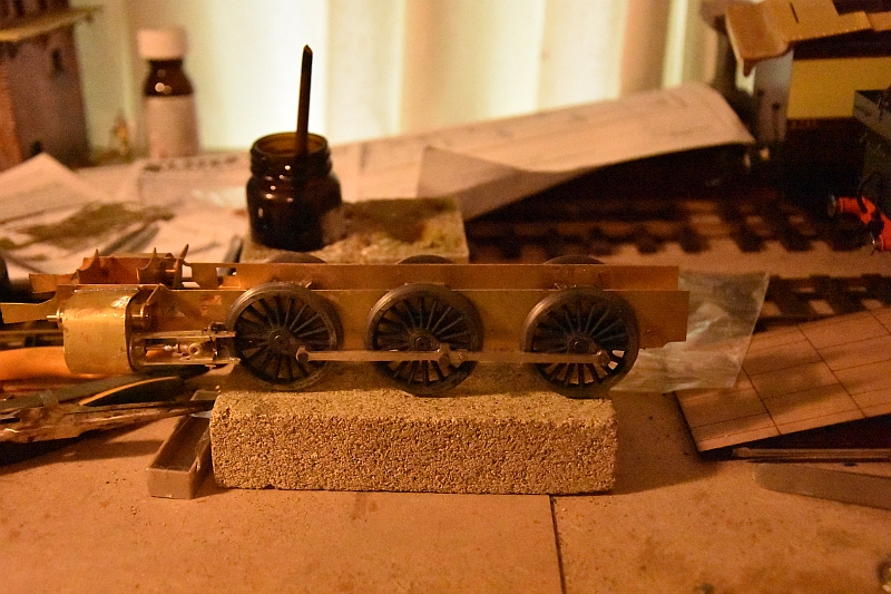
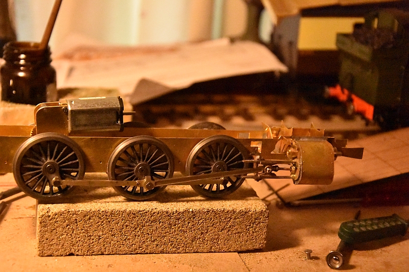
All six horn blocks have now been put together. The axles and wheels have been offered up to the chassis to check for free wheeling – all seems ok. The next job is to fix the con rods in place down each side to check for clearance and correct wheel alignment as show here in the attached image. Pleased to say that all seems to be ok so far. The next part is to connect the con rods from the pistons to the central wheels and check for ease of movement through a complete rotation of the wheel sets
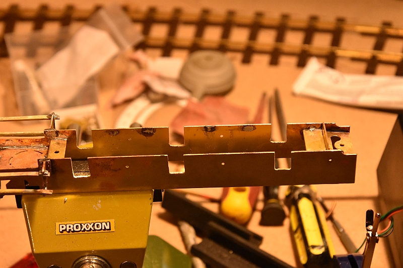
The running plate is put together and comprises of three parts for the top where the boiler and firebox will sit, two sides and a front buffer plate and a back plate. 208 rivets are put along the running plate sides before all is soldered together as shown here.
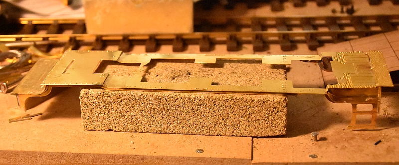
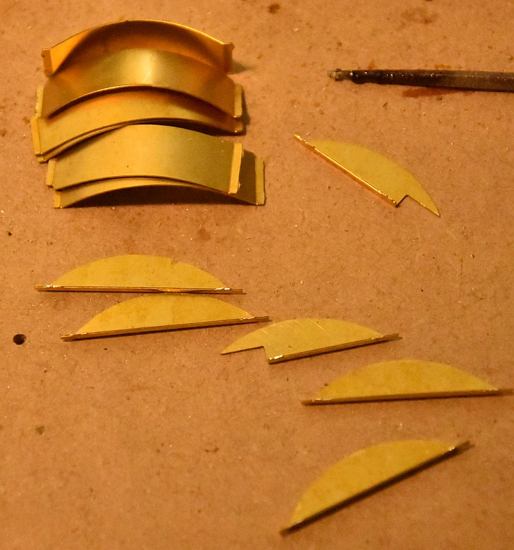
The Splashers side plates and tops are next to be soldered to the chassis, (these are cut from the etches supplied). The edges of both are hinged to add a beading effect to them as shown here
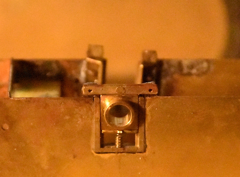
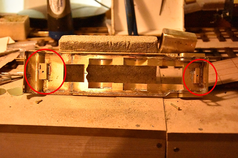
Finally, two brackets need to be made up with
nuts soldered to them to hold the chassis to the body, (circled in
red), as shown here.
Associated traders
Walsall Model Industries